ZK-1001U Amplifier Enclosure
por David Dover en Thingiverse
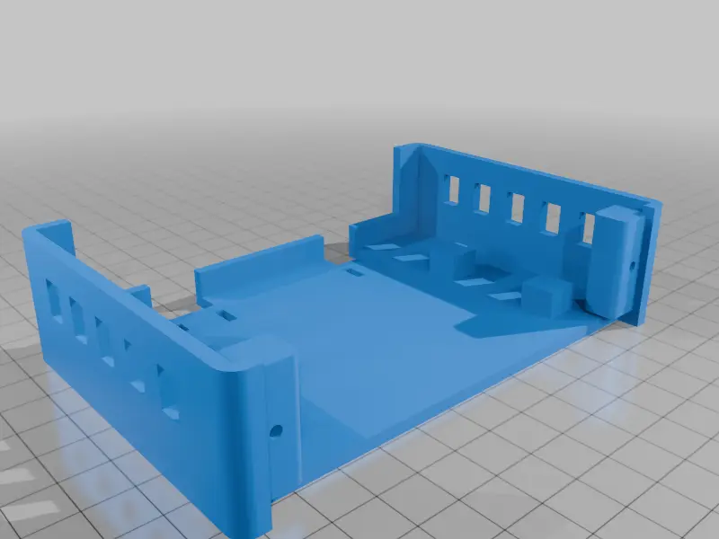
ZK-1001U ONE-PIECE DROP-IN AMPLIFIER CRADLE - prototype PRINT: Single STL, upright on its bottom, open side facing upward. PETG recommended; 0.2-mm layers, 3-4 walls, 20-30% infill. No lid. No support expected for side vents, but inspect slicer preview (horizontal pilot bores may bridge). Outer...
Licencia
Uso comercial permitidoCC BY-SA 4.0 — Atribución, compartir igual
Puedes usarlo y modificarlo dando crédito; las versiones modificadas deben compartirse con la misma licencia.
Al descargar aceptas respetar la licencia y dar crédito a David Dover.
Archivos (1)
- Categoría
- Para tu impresora
- Formatos
- STL
- Descargas
- 0
- Publicado
Sobre este modelo
ZK-1001U ONE-PIECE DROP-IN AMPLIFIER CRADLE - prototype PRINT: Single STL, upright on its bottom, open side facing upward. PETG recommended; 0.2-mm layers, 3-4 walls, 20-30% infill. No lid. No support expected for side vents, but inspect slicer preview (horizontal pilot bores may bridge). Outer body approximately 124 mm wide x 84 mm deep x 31 mm tall. 3-mm walls/floor. Rounded outer corners. Top fully open; large opening at rear permits screwdriver access to power / speaker screw terminals. FRONT MOUNT: Fits style of metal faceplate with rounded ends; published drawing: 115.5 mm overall width, 22.8 mm height, 105-mm distance between 3.2-mm mounting-hole centers. Faceplate attaches to two integrated upright side tabs. Front-facing pilot bores are 2.5 mm diameter for approximately M3 self-tapping plastic screws (test fit; do not force). These are horizontal, not vertical, to correspond with the flange holes. Faceplate bottom assumes approximately Z=5 mm (hole centers Z=16.5 mm). Board lies behind front, rests on pads approx Z=10 mm. Board holes not assumed or drilled. REAR CHASES: Speaker: 14-mm wide opening, center x=-27 mm. Power: 12-mm wide opening, center x=+27 mm. Chases pass through the lower rear wall and underside edge. Floor wire-tie slots near rear for optional strain relief. IMPORTANT: This is a dimension-based prototype, not verified on the specific amplifier in hand. Published variants differ in PCB, flange thickness, screw-hole position and connector details. Do a quick test fit before final assembly. Use insulating board supports and keep airflow clear; avoid hot components touching plastic and avoid exposed conductors.
Descripción original del autor, publicada en Thingiverse.