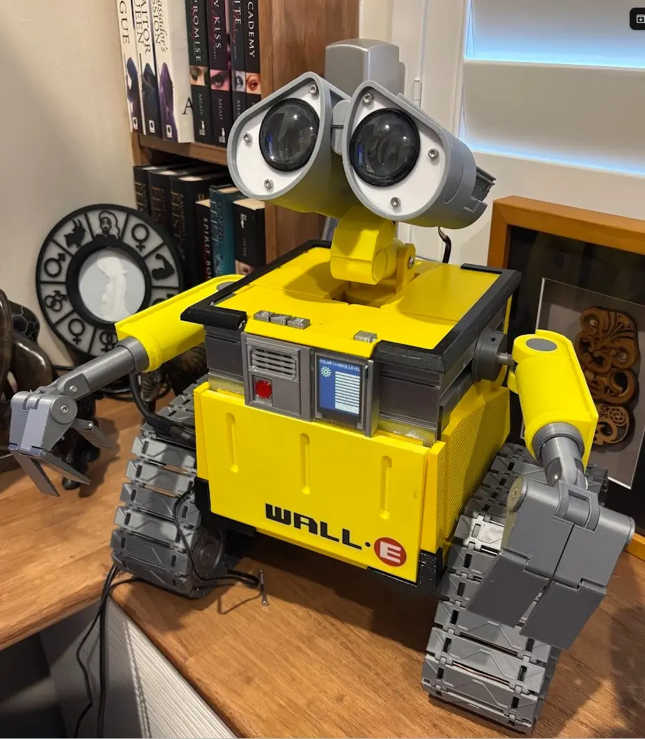
Wall-E 3D Model (WIP)
por Gary en Printables
My set of STLs for my WALLE Model I made for my son
Licencia
Uso comercial permitidoPuedes imprimirlo, modificarlo y venderlo dando crédito al autor.
Al descargar aceptas respetar la licencia y dar crédito a Gary.
Archivos (138)
- Main body back.stl STL · 159 KB
- Back Door Handle.stl STL · 28 KB
- Back Door Handle 2.stl STL · 33 KB
- Back door pipe.stl STL · 74 KB
- Back Door Top.stl STL · 53 KB
- Back Door Bottom.stl STL · 50 KB
- New Button.stl STL · 48 KB
- Button Cover.stl STL · 65 KB
- Dipswitch mount.stl STL · 53 KB
- Left front Panel.stl STL · 77 KB
- PICO Post 1.stl STL · 41 KB
- PI Mount.stl STL · 58 KB
- Pi Mount Post.stl STL · 25 KB
- Front Panel Holder.stl STL · 170 KB
- Body Main support.stl STL · 57 KB
- 10mm Pipe cover.stl STL · 71 KB
- Front axil holder Top 1.stl STL · 41 KB
- Wheel Sidelock 2.stl STL · 58 KB
- Main Guide Track 1.stl STL · 75 KB
- bottom spacer 3.stl STL · 43 KB
- bottom spacer 1.stl STL · 52 KB
- 10mm pipe x 116mm.stl STL · 69 KB
- bottom spacer 2.stl STL · 52 KB
- Bottom Axil Holder 1.stl STL · 50 KB
- 16mm pipe x 54mm.stl STL · 86 KB
- Rear wheel support 1.stl STL · 202 KB
- Wheel Sidelock 3.stl STL · 58 KB
- bottom spacer 4.stl STL · 43 KB
- Bottom Brake.stl STL · 24 KB
- Bottom Axil Holder 2.stl STL · 50 KB
- Wheel main support.stl STL · 54 KB
- Front wheel support 2.stl STL · 174 KB
- Front wheel support 1.stl STL · 174 KB
- 16mm pipe cover.stl STL · 75 KB
- Front axil holder Top 2.stl STL · 41 KB
- Leg Bar.stl STL · 25 KB
- top spacer 2.stl STL · 52 KB
- top spacer 3.stl STL · 52 KB
- Main wheel Mount.stl STL · 62 KB
- Rear wheel support 2.stl STL · 202 KB
- Main Guide Track 3.stl STL · 75 KB
- Main Guide Track 2.stl STL · 75 KB
- top spacer 4.stl STL · 52 KB
- Wheel Sidelock 1.stl STL · 58 KB
- Wheel Sidelock 4.stl STL · 58 KB
- Wheel Sidelock 5.stl STL · 58 KB
- Wheel Track.stl STL · 68 KB
- Left Wheel stls.stl STL · 1,8 MB
- Main Guide Track 4.stl STL · 75 KB
- Wheel Sidelock 6.stl STL · 58 KB
- Top shaft holder.stl STL · 170 KB
- top spacer 1.stl STL · 52 KB
- Wheel Sidelock 7.stl STL · 58 KB
- Wheel Sidelock 8.stl STL · 58 KB
- E.stl STL · 2 KB
- E Background.stl STL · 23 KB
- Black letters.stl STL · 11 KB
- Main Body Front door.stl STL · 107 KB
- Finger 2.stl STL · 93 KB
- Shoulder 3.stl STL · 102 KB
- Categoría
- Varios
- Formatos
- STL
- Descargas
- 2,372
- Publicado
Sobre este modelo
This is my stl file set of a Wall-E model I made for my son. Included so far: - Head - Neck - Main body - Right arm (mirror parts for left) - Front door - Left wheel/leg structure (mirror for right side)
I also used some aluminum pipe, steel pins, and a threaded bar for this build. All the hex screws are spares from Prusa printer builds. Extra parts required: Most of the screws used are all the M3 hex screws spare from my Prusa printer assembly A. Head - 28mm long 6mm steel pin to connect the eye/nose construction to the neck - 6mm threaded steel bar with a nut on either end
Screws (eyes and connector): - M3 * 6mm x 4 pieces - M3 * 8mm x 8 pieces - M3 * 12mm x 1 piece (right eye) - M3 * 16mm x 1 piece (left eye) - M3 * 25mm x 4 pieces
B. Lens I've used 2 sets of lens for my build. One glued to the “iris” and another to the outside. Dimensions (Plano-convex Condenser Lens Focal Length Optical Glass): - Size (D*H): φ28mm * 6mm - Size (D*H): φ40mm * 9mm
I purchased mine here C. Neck Screws - M5 x 16r screw (2x) - M3 x 30mm + hex nut
There's also space for a grub screw near the base of the neck but I haven't had any need to use one. D. Main Body Before attaching the head construction, prep the main body frame. Main Body Frame - M3 x 25mm (4x) - Superglue
Top cover - attached to neck assembly - M3 x 12mm (4x)
E. Arm (one side) - 2.5mm x 27mm (3x) - fingers - M3 x 10mm (2x) - secure the sides of hand - 10mm x 60mm aluminium pipe - hand - M3 x 25mm - secure shoulder to arm - 8mm x 60mm aluminium pipe - shoulder - 4mm grub screw (3x) - shoulder joint - M3 x 10mm (2x) - secure 2 posts that hold the arm in place - M5 x 16r screw - fix the hand to the arm
Mirror the arm parts to make the other side. F. Front Panel Assembly - M3 x 6mm (2x) - M3 x 12mm - M3 x 18mm (2x) - fix the panel to the front
G. Neck to main body top Panel - M3 x 12mm (4x)
H. Back door - M3 x 25mm (2x) - secure back door handle - 5mm x 25mm (4x) - hold back door trimmings to back door - 5mm x 150mm - secure back door to main top panel - M3 x 12mm (6x) - secure sides to the top - M3 x 18mm (6x) - secure top panel to sides
I. Front Door - 5mm cubic ferris magnet (4x) - 8mm x 178mm aluminium pipe - M3 x 10mm (4x) - secure bottom trimmings to base
J. Wheels - M3 x 10mm (8x) - to lock the wheels - 10mm pipe x 116mm - bottom long shaft - 10mm pipe x 70mm - top long shaft - 10mm pipe x 56mm (2x) - axils used for the top guides - 10mm pipe x 64.00 mm - axil - bottom guide front - 10mm pipe x 61.00 mm - axil - bottom guide back - 5mm x 55 mm steel pin - holds the bottom in place - 5mm x 25.40 mm steel pin - holds the top in place - 8mm x 19mm pipe - 5mm x 24mm - used to secure the leg assembly to the base
Wheel tracks - print 29 or 30 per side I used thick copper wire or paperclips to connect the tracks together - M3 x 25mm (8x) - secure the wheel assembly (left and right) to the base - M3 x nuts (8x)
K. Electronics The electronics runs on a Rasberry Pi Zero 2W (with headers). Its connected to a mono speaker that has a class D amp and a single switch connected to the red button in front. - 1.8" TFT Display Breakout and Shield - Raspberry Pi Zero 2W with Header - Adafruit STEMMA Speaker - EYESPI breakout board - EYESPI Cable - SPDT 125V 3A Sub-Miniature Micro Switch with Lever - 150mm Socket to Socket Jumper Leads
Display wiring: - Pi 3V to breakout VIN (red wire) - Pi GND to breakout GND (black wire) - Pi SLCK (GPIO 11) to breakout SCK (blue wire) - Pi MISO (GPIO 9) to breakout MISO (green wire) - Pi MOSI (GPIO 10) to breakout MOSI (yellow wire) - Pi CE0 (GPIO 8) to breakout TCS (purple wire) - Pi GPIO 25 to breakout DC (white wire) - Pi GPIO 24 to breakout RST (pink wire)
Switch Wiring: - Pi GND (use the one opposite GPIO 27) - Pi GPIO 27
Speaker wiring: - Pi 3.3 V - Pi GND - Pi GPIO 18
Steps to program Pi to follow!
Descripción original del autor, publicada en Printables.