Turboprop Engine
por motoo kondo en Thingiverse
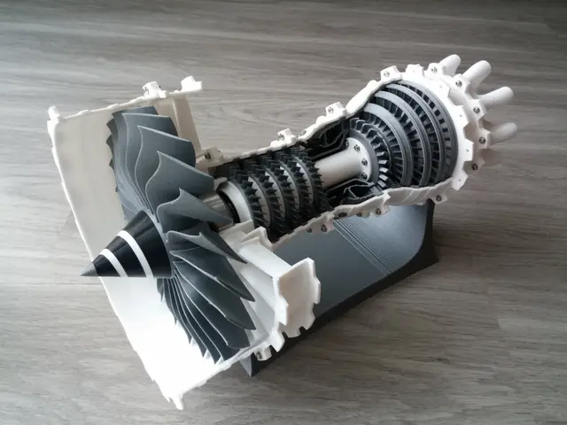
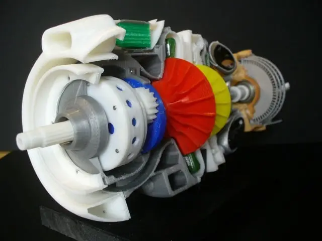
This is a cutaway model of Turboprop Engine having following features for educational purpose. Features are: (1) Centrifugal (Impeller type) compressor (2) Can type Combustion Chamber (3) Axial Flow Turbine (4) Reduction gears and propeller shaft (5) Air inlet cowling with Oil Cooler Air Passage...
Licencia
Solo uso personalCC BY-NC 4.0 — Atribución, no comercial
Puedes imprimirlo y modificarlo para uso personal dando crédito. No se permite vender las impresiones.
Al descargar aceptas respetar la licencia y dar crédito a motoo kondo.
Archivos (76)
- Part_List_Index_No.xlsx XLSX · 11 KB
- Accy-Parts-SM-Base101.stl STL · 45 KB
- Oil-Cooler-Inlet201.stl STL · 197 KB
- Accy-Parts-FMU101.stl STL · 71 KB
- Comp-Inter-Case01.stl STL · 1,8 MB
- Reduction-Gear03.stl STL · 275 KB
- Interm-Case03a.stl STL · 282 KB
- Turbine-Case01b.stl STL · 210 KB
- Turbine-HP-NGV01.stl STL · 225 KB
- Imp-Coupling01.stl STL · 133 KB
- Shaft-Coupling03.stl STL · 71 KB
- Interm-Case02a.stl STL · 254 KB
- Oil-Cooler101.stl STL · 82 KB
- Turbine-Shaft-Spacer02.stl STL · 29 KB
- Interm-Case-Cut01.stl STL · 420 KB
- Comp-LP-Diffuser01.stl STL · 68 KB
- Accy-Parts-SM101.stl STL · 61 KB
- Turbine-IP-Rotor01.stl STL · 489 KB
- Reduction-Gear-Flg02.stl STL · 326 KB
- Turbine-IP-NGV01.stl STL · 343 KB
- Accy-Parts-RH-Base101.stl STL · 113 KB
- Turbine-Case01a.stl STL · 465 KB
- Reduction-Panel01a.stl STL · 11 KB
- Turbine-LP-Rotor01.stl STL · 465 KB
- CC-Aircase03.stl STL · 333 KB
- CC-Aircase04.stl STL · 453 KB
- Accy-Parts-SM102.stl STL · 26 KB
- Turbine-LP-NGV01.stl STL · 429 KB
- Air-Intake-Cover101.stl STL · 219 KB
- Shaft-Brg-Spt02.stl STL · 26 KB
- Shaft-Spacer201.stl STL · 30 KB
- Reduction-Panel03.stl STL · 61 KB
- Stand102.stl STL · 15 KB
- Turbine-HP-Rotor01.stl STL · 471 KB
- Air-Intake-Fairing101.stl STL · 349 KB
- Reduction-Gear-Flg01.stl STL · 103 KB
- Outlet-Elbow02.stl STL · 62 KB
- Shaft-Coupling01.stl STL · 26 KB
- Oil-Cooler-Outlet101.stl STL · 362 KB
- Interm-Case-Cut02.stl STL · 91 KB
- Reduction-Gear01b.stl STL · 350 KB
- Stand101.stl STL · 50 KB
- Accy-Parts-PCU101.stl STL · 114 KB
- Reduction-Panel02.stl STL · 88 KB
- Reduction-Panel01.stl STL · 133 KB
- Air-Intake-Case101.stl STL · 1,7 MB
- Impeller-HP02.stl STL · 666 KB
- Reduction-Gear02.stl STL · 568 KB
- CC-Flame-Tube03x95m.stl STL · 582 KB
- Comp-HP-Diffuser01.stl STL · 70 KB
- Part_List_ABC_Seq.xlsx XLSX · 12 KB
- Oil-Cooler102.stl STL · 431 KB
- Comp-Outlet-Case101.stl STL · 1,2 MB
- Turbine-Shaft01.stl STL · 505 KB
- Reduction-Gear01a.stl STL · 528 KB
- Air-Intake-Cowling02.stl STL · 162 KB
- Shaft-Brg-Spt01.stl STL · 31 KB
- Shaft-Spacer04.stl STL · 34 KB
- Oil-Press-Tx01.stl STL · 209 KB
- Air-Intake-Cowling301.stl STL · 1,5 MB
- Categoría
- Educación
- Formatos
- XLSX, STL, PDF
- Descargas
- 68,595
- Publicado
Sobre este modelo
This is a cutaway model of Turboprop Engine having following features for educational purpose. Features are: (1) Centrifugal (Impeller type) compressor (2) Can type Combustion Chamber (3) Axial Flow Turbine (4) Reduction gears and propeller shaft (5) Air inlet cowling with Oil Cooler Air Passage Download files includes; -files: STL Files -images: STL File Figure and Index Picture for assembly Aid Purchase Parts Information; -Bearings WBC6-12ZZ (6 x 12 x 4) 6ea - Assemble to outer holes of each Panel F686ZZ(6 x 1 3x 5) 2ea - Assemble to center of each Panel 689ZZ (9 x 17 x 5) 2ea - For LP and HP Impeller 6900ZZ (10 x 22 x 6) 2ea - For Prop-Shaft, Turbine Shaft -Aluminum Tubes 9mm dia x Appox. 70mm - as Compressor Rotor Shaft (Make slots both ends) 6mm dia x Appox. 100mm - as Turbine to Compressor Coupling Shaft -Screws Micro screws M1.4x3L - Appox. 70 ea - Direct screw-in to 1 mm dia hole (No nut), Head side flange hole is 1.5 mm dia. Screws M2 x 20L - 1ea - M2 Tap is used - Starter associate parts Screws M2 x 10L - Appox. 12ea - M2 Tap is used - Red. Gear Panels associate parts and IGV Screws M2 x 6L - Appox. 4ea - M2 Tap is used - Diffusers and Turb. Shaft Coupling Assembly Points - Rotors, Gear Train Set and Casings can be assembled and adjusted separately. - Combustion Air Casing is slid to the outlet elbow assembly until aft end clears from the turbine case its bore at first. Then slide back to bore. Gluing is optional. - Standard Skill (such as Drilling, Tapping, Filing, Tightening, Painting and Gluing etc) is needed and perseverance too.
Total Net Print Time: Approx. 50 HR - (Estimated as case of PLA, 0.4mm Nozzle, 0.2mm Layer Height, 40% infill and No raft and support) Note: When at actual print, each parameter may be adjusted.
[Update] 2018.8.13 This is the original design for the followings. Please refer them. - Mod Parts : https://www.thingiverse.com/thing:2416610 - Mod Parts2 : https://www.thingiverse.com/thing:2747907 - Mod Parts3 : https://www.thingiverse.com/thing:2792220 [Update] 2018.8.22 Add "Assembly Charts" (pdf format) and figures are added to assist for assembly. [Update] 2018.9.4 Parts List including Mod-Parts and Identification of rotaing parts. [Update] 20180913 Add the optional part "Reduction-Panel03f" for "Reduction-Panel03" [Update] 20181025 Add "Mount-Foot101" called in "Assembly Charts" [Update] 20190907 I have prepared the detailed Assembly Manual as an option for those who want to build this engine with a small amount of money. Please browse if you are interested in this. https://cults3d.com/en/3d-model/tool/turboprop-engine-assembly-manual-option [Update]20200506 "Flange-Screw01" figure added about M1.4 Screw. [Update]20201018 Add "Shaft-Coupling 101.stl" having thicker wall.
Descripción original del autor, publicada en Thingiverse.