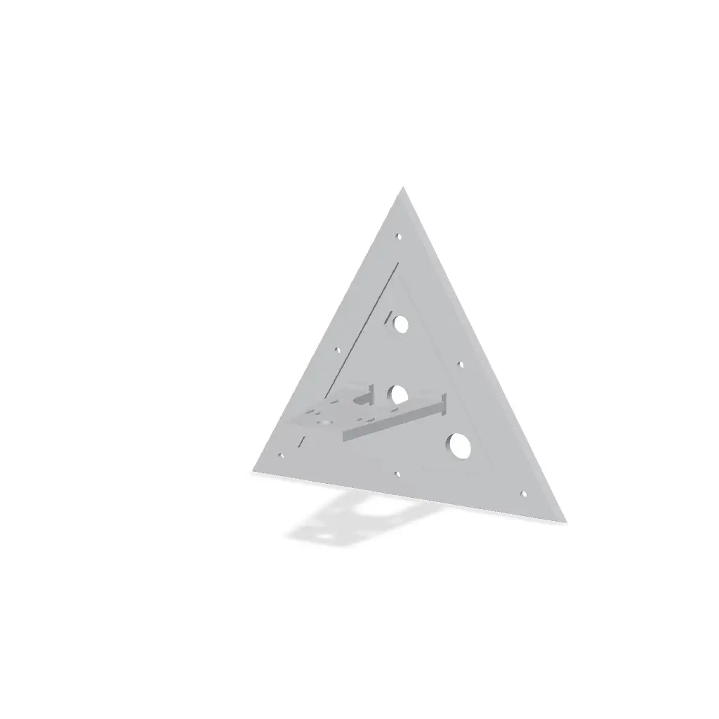
TreeNode 2-piece: Solar LoRa Enclosure (Prototype)
⚠ Prototype: untested. This design has not been printed, water-tested or IP-rated yet. Treat it as a starting point, not a proven weatherproof enclosure. All images are CAD renders; there are no print photos yet. If you print it, please post a make and tell me what needed fixing.
Thangs entrega los archivos a usuarios con cuenta gratuita
Licencia
Solo uso personalCC BY-NC-SA 4.0 — Atribución, no comercial, compartir igual
Uso personal dando crédito; sin fines comerciales y las modificaciones con la misma licencia.
Al descargar aceptas respetar la licencia y dar crédito a Just S.
Archivos (2)
- piece1-hatch-tower.stl STL · 402 KB
- piece2-shell.stl STL · 75 KB
- Categoría
- Tecnología
- Formatos
- STL
- Descargas
- 3
- Publicado
Sobre este modelo
⚠ Prototype: untested. This design has not been printed, water-tested or IP-rated yet. Treat it as a starting point, not a proven weatherproof enclosure. All images are CAD renders; there are no print photos yet. If you print it, please post a make and tell me what needed fixing.
What it is TreeNode 2-piece is a sealed, triangular (tetrahedron) solar enclosure for a Heltec T114 LoRa node running Meshtastic or MeshCore. It hangs from a tree or post by an 8 mm eyelet at the apex. Three small solar panels sit in pockets on the three sloped faces. The electronics mount on a sled that comes out with the bottom hatch.
Assembled, it's a tetrahedron with 240 mm edges, about 196 mm tall. Walls and hatch are 6.35 mm (1/4 in) thick, because the design started as a CNC-cut polycarbonate box.
It prints as 2 pieces:
Piece 1: piece1-hatch-tower.stl (about 240 x 208 x 113 mm). The bottom hatch fused with the internal electronics sled (the "tower"). Piece 2: piece2-shell.stl (about 232 x 201 x 190 mm). The shell with 3 solar-panel pockets, an internal screw rim and the apex hanger eyelet. The sled, its feet and the hanger are fused into these two pieces, so there are only two parts to print. The screws and inserts are bought parts, and the gasket is cut from sponge sheet.
Printing Material: ASA is recommended for outdoor UV exposure. PETG is acceptable. Nozzle: 0.4 mm Perimeters/walls: 5-6 Top/bottom layers: 5-6 Infill: 30-40% gyroid Reinforcement: add solid infill (or a modifier) around the 6 screw holes in the hatch and around the 6 insert sockets in the shell rim. Bed size: both pieces are large. Piece 1 is 240 x 208 mm as exported, so you need a bed of roughly 250 x 250 mm or larger. Supports: you will need supports. The best orientation is up to you and your slicer. Reference orientation: the STLs are exported in the modelled (assembled) orientation. Each one has a large flat face to put on the bed: Piece 1 sits on the hatch exterior, a solid 240 mm triangle, with the tower pointing up. It has only small bridges: the ceilings of the screw-head recesses and the tops of the sled slots. Piece 2 sits on its open base, a flat triangular ring, with the apex pointing up. In the STL this face sits at z = 6.35 mm (its assembled height), not z = 0; your slicer drops it onto the bed. It has a small flat downward-facing area under the apex hanger (about 200 mm²), plus the undercut solar dovetail grooves and the cable openings on the sloped walls. Check your slicer's support preview. Insert sockets: printed holes usually come out slightly undersized, and the 6 mm insert sockets have no extra clearance, so test-fit the inserts and open the sockets slightly if needed. Hardware As an Amazon Associate I earn from qualifying purchases.
Parts list on Amazon: https://amzn.to/4hoUUdr
Enclosure
6x M4 x 0.7 x 10 mm DIN 7984 low-head socket cap screws, stainless. The hatch recesses are 7.5 mm wide x 3 mm deep, so standard cap heads and countersunk heads won't fit. 6x M4 brass knurled inserts, 4 mm long x 6 mm OD 2-part 5-minute epoxy 1/8 in (3.2 mm) closed-cell neoprene sponge sheet, for the hatch gasket 3M Marine 4000UV sealant Solar
3x MECCANIXITY 6V 1.68W solar panels, 110 x 92 mm (the pockets are 111 x 93 x 1.5 mm) 3x 1N5817 Schottky diodes (one per panel) Hatch penetrations
M12 x 1.5 IP68 breather vent 12 mm waterproof momentary push button USB-C bulkhead U.FL to N-type female pigtail + ALFA AOA-915-5ACM 915 MHz antenna Electronics
Heltec T114 UNIKARO 3.7V 15000 mAh battery JST 2-pin pigtails: one build uses two 1.25 mm leads and one 2.54 mm lead (the T114 also ships with two 1.25 mm leads) Hatch ports The hatch has four round through-holes, modelled at these nominal sizes:
A: 16 mm, centre. Antenna (N-type bulkhead), directly below the sled's arched opening. B: 12 mm (x = 0, y = 48 mm, toward a corner). Breather vent, with a hex nut pocket on the inside. C: 18.5 mm (x = +45, y = -28 mm). USB-C bulkhead. D: 12 mm (x = -45, y = -28 mm). 12 mm push button. Port B has a hex nut pocket on the inside (top) face of the hatch: 18.4 mm across flats and 3.35 mm deep. The vent's nut drops into the pocket and is held there, so you can tighten the vent from outside by its 18 mm head.
Key dimensions (mm) Tetrahedron: edge 240, height about 196. Wall and hatch thickness 6.35. Internal screw rim: inside the shell, just above the hatch. 6.35 thick, 22 wide. The opening through the rim is a triangle with sides of about 125 at its narrowest. Screws: 6 in total, 3 at mid-edge and 3 near the corners. Hatch holes: 4.5 clearance with 7.5 wide x 3 deep head recesses. Rim holes: 4.5 clearance with 6 dia x 4 deep insert sockets that open upward, into the shell. Sled: 100 tall, 76 wide at the base, 42 at the top, 6.35 thick. It stands on two 18 x 14 x 6.35 feet. It has: a 32 mm-wide arched antenna opening, with the crown about 42 above the hatch top face 4 battery-strap slots (3 x 12, 44 apart, 30 vertical pitch) 2 board-strap slots (3 x 8, 30 apart) a 10 mm cable hole near the top Sled clearance: the bare sled passes through the rim opening with only about 1.4 of margin at the tightest point. Keep the electronics and cables within the sled's outline when you pull the hatch. Solar pockets: 111 x 93 x 1.5 deep. A continuous dovetail groove runs around each pocket: 8 wide at the mouth, 10 wide at the base, 3 deep from the face. Each face also has one 19 x 25 cable opening. Apex eyelet: 8 mm bore. Assembly 1. Threaded inserts (shell rim)
The 6 insert sockets (6 mm dia x 4 mm deep) face upward into the shell. Install the inserts from inside the shell, reaching in through the base opening. A soldering iron can't get a good angle in there, so don't heat-set them. Set them with 5-minute epoxy instead.
Test-fit each insert. If a socket is tight, open it up slightly with a 6 mm drill. Put a small amount of epoxy in the socket, press the insert in flush, and keep epoxy out of the threads. Let it cure fully before you fit any screws. The screws come up through the hatch and rim and pull each insert down against the rim. The epoxy mainly holds the inserts in place and stops them spinning; it doesn't carry the clamping load.
2. Hatch gasket
The hatch has a gasket groove on its top face (the face that seats against the rim):
An equilateral-triangle loop, 4 mm wide x 2.4 mm deep 156 mm outer sides and 142.2 mm inner sides, a centreline length of about 447 mm Cut a 4 mm wide strip from the 1/8 in (3.2 mm) closed-cell neoprene sheet and lay it into the groove. You can either cut a single triangle ring (156 mm outer / 142.2 mm inner) or butt-join a strip. At 2.4 mm groove depth, the 3.2 mm sponge compresses by about 25%.
3. Solar panels
Route each panel's leads through the 19 x 25 mm cable opening behind its pocket. Fill the continuous dovetail groove around the pocket with 3M Marine 4000UV, then press the panel into its pocket. The sealant bonds the panel and locks into the dovetail. Seal each cable opening from behind the panel so it's fully closed. 4. Wiring
Solar: wire the 3 panels in parallel, each through its own 1N5817 diode (band/cathode toward the common + line), then to the T114 solar input (1.25 mm 2-pin JST). Check polarity against the board's + marking before plugging in. Battery: the UNIKARO battery has a 2.54 mm plug, but the T114 uses 1.25 mm. Use an adapter made from the 1.25 mm and 2.54 mm pigtails, or the lead that comes with the board. Check polarity here too. Antenna: connect the U.FL to N-type pigtail to the T114 and mount the N-type bulkhead in port A. The ALFA antenna screws onto it outside, under the hatch. Mounting: strap the battery and board to the sled through the strap slots, and fit the breather, button and USB-C bulkhead in the hatch ports. 5. Close up
Seat the hatch (gasket up) against the rim. Tighten all 6 screws evenly, working around the hatch a little at a time, until the gasket is compressed. Don't over-tighten into the printed parts.
Caveats Prototype. Nothing here has been print-tested, water-tested or IP-rated yet. Not airtight on purpose. The breather equalizes pressure, so the box is intentionally not airtight. Solar voltage. Heltec recommends roughly 5 V panels (6.5 V max) for the T114. The 6 V panels work through the diodes, but that leaves limited margin. Seal every penetration: the solar cable openings, the panel edges, and every hatch bulkhead (antenna, USB-C, button, breather). An open cable opening defeats the whole seal. Check the gasket. Confirm the gasket compression with all 6 screws fitted and check for gaps before you deploy. Sled strength. The sled is fused to the hatch through printed layers, which is the weakest direction for bending. Support the battery well and test it under load. Hanger strength. The apex hanger/eyelet has not been load-tested. Proof-test it before trusting it outdoors. Thin walls by the grooves. The material beside each solar dovetail groove is thin (about 0.6 mm at the undercut on the left and right sides). Print it with good wall settings and handle it with care. Source Designed in Zoo Design Studio (KCL).
License: Creative Commons Attribution-NonCommercial-ShareAlike 4.0 (CC BY-NC-SA 4.0)
Descripción original del autor, publicada en Thangs.