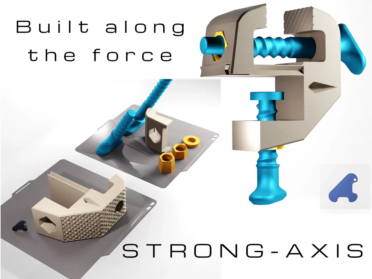
‘STRONG-AXIS’ workbench vice - Built along the force
por Tomishape en Printables
The challenge with this model: greater robustness!
Licencia
Solo uso personalCC BY-NC 4.0 — Atribución, no comercial
Puedes imprimirlo y modificarlo para uso personal dando crédito. No se permite vender las impresiones.
Al descargar aceptas respetar la licencia y dar crédito a Tomishape.
Archivos (8)
- Categoría
- Herramientas
- Formatos
- STL, 3MF
- Descargas
- 7
- Publicado
Sobre este modelo
‘STRONG-AXIS’ workbench vice - Built along the force Link to my TikTok video:https://www.tiktok.com/@tomishape/video/7703229853667020065 - The challenge with this model: greater robustness!
In May 2026, I published the ‘STRONG’ workbench vice design, a tool-oriented model made as robust as possible. A user then contacted me to say that their printed version hadn’t withstood the stresses: a screw had sheared and the main block had split. I was very disappointed, as I’d wanted to offer something truly robust. It kept niggling at me, so I gave it some thought: the main body needed to be printed in the direction of the forces exerted on the vice. But how? Then I had an idea: to print the main body flat, and separate the nuts so they could be printed individually in the direction of the screw thread. All that remains is to insert these nuts into the two main parts of the vice (see diagram opposite). This time, I opted for a screw diameter of 20 mm (measured at the thread groove, compared to 15 mm for the previous ‘Strong’ version). The model is therefore bulkier, but it’s still within reasonable limits. The screws are printed at a 30° angle (see the appendix for the increase in strength achieved by printing at 30° along the screw axis), which allows for the small overhangs that appear during slicing, whilst maintaining a functional thread. - Summary of technical specifications
• The main body (VICE A) and the sliding section (VICE B) are 3D-printed flat, with print layers parallel to the clamping screw. • Separate nuts are inserted into VICE A and VICE B. Their frustoconical outer shape locks them into their respective recesses. • The screws (for clamping parts A and B, and for clamping to the workbench) have a diameter of 20 mm. They are printed at an angle of 30° to the vertical, to avoid layers being perpendicular to the axis of tension. • Particular care has been taken with the design of the nut/screw threads. • An end stop, to be fitted onto screw A, distributes the clamping force across the workbench. • A single, simple support on the ‘Vise B’ component - Component dimensions
• Main body (VISE A): 152 mm (L) × 168 mm (H) × 70 mm (D) • Sliding body (VISE B): 80 mm × 45 mm × 85 mm (D) • Maximum screw length: 210 mm (screw B) An illustration of the complete model assembled on a 256 mm × 256 mm base plate is available in the photos (see ‘scale comparison’). - Aesthetics
I like to give my designs a bit of ‘character’. Here, two elements stand out: • a texture with small protrusions on the outer surface of VISE A; • the option for customisation. I suggest: VISE A + B = colour 1; nuts A + B = colour 2; screws A + B = colour 3. - Printing
• VISE A and B: at 40 per cent density, the gains in strength are close to their practical limit. Beyond that, the improvement is only marginal and printing takes longer, particularly as the layers here are oriented in the same plane as the forces. • Screws A and B: as their cross-sectional area is comparatively small, I recommend an infill of 80 per cent (as a reminder, they are angled at 30° to the vertical), which offers a real advantage in terms of tensile strength along the axis. NOTE: ‘The presentation rendering is a computer-generated image, but the print has been simulated in the slicer to ensure a satisfactory result. My extensive experience allows me to determine whether, by following my setting recommendations, the print will turn out well. You can find an image of the slicing simulation in the photos. I haven’t been printing for quite some time now; I’m focusing on modelling complex designs. If you have any questions, I’m fully available via the Printables messaging system.” Happy printing! Print settings All parts were printed with a layer height of 0.30 mm, a 0.6 mm nozzle, and the ‘Strength’ profile in Bambu Studio. The settings below are recommendations for each part, based on the mechanical role of each component. SCREW A ‘Withstands all bending and tensile clamping forces on both arms. The organic lateral profile distributes stresses more evenly than a flat-walled frame.’ • No support Parameter Recommended value Nozzle 0.6 mm Layer height 0.3 mm 1st layer 0.35 mm Outer wall width 0.55 mm Inner wall width 0.62 mm Fill width 0.62 mm Number of walls 4 Upper shell thickness | 1.2 mm Top 4 layers Bottom 4 layers Infill 40 % Infill pattern Gyroid Outer speed 60 mm/s Inner speed 60 mm/s Infill 80 mm/s T ravel 200 mm/s - Wall order for this model: Inner → Outer - Wall generator: classic mode - Joint position: Aligned Quality settings I would tick: ✅ Detect Thin Walls ✅ Arc fitting (if available) ✅ Monotonic Top ✅ Avoid crossing walls ✅ Wipe whilst retracting ✅ Enable Z-hop only during retracts SCREW B ‘Moves within the slide of body A and accommodates the thread of screw A. Printed with the teeth facing upwards to handle overhangs cleanly — without supports. ” Settings: Same as VICE A (infill = 40%) • With support: fine tree-like structure only for part VICE B (see slicing image in photos) SCREW + NUT + END CAP NUT A: Transmits the clamping force via its threads. The component subject to the highest torsional stress. A high density or solid core is strongly recommended. NUT B: Compression and torsion only. Subject to less stress than screw A — same parameters for consistency. • Without support • Parameters: Same as SCREWS A + B, except for fill factor (fill factor = 80%) • Joint: the closest possible. (to avoid a line on the screw threads) - Adhesion: Outer edge 6 mm (especially for screws inclined at 30° to the vertical).
Why use gyroid filling? A gyroid is a continuous, curved surface that winds through the interior of the part in all three directions simultaneously. Unlike grid or rectilinear infill — which are strong along their axes but weak diagonally — the gyroid offers quasi-isotropic strength: it resists forces uniformly regardless of their direction. For a vice, where clamping simultaneously generates tensile, bending and shear forces, this is a tangible advantage. At 40 per cent density, the gains in strength are close to their practical limit. Going beyond this point yields only a marginal improvement, whilst significantly increasing print time. The walls bear the bulk of the load — four perimeter layers with a 0.6 mm nozzle already amount to 2.4 mm of solid material on each face. PLA or PETG? | Ease of printing | Easy | Moderate | | Compressive strength | Higher | Slightly lower | | Impact resistance | Brittle | Tough | | Heat resistance | ~55 °C max | ~80 °C max | | Long-term stability | Good | Excellent | Tip: Dry your PETG spool before printing (8 hours at 65 °C). Moisture causes poor layer adhesion — the main cause of failure for threaded parts. Francais Etau d'établi "STRONG-AXIS" - Built along the force Mon lien TikTok video: https://www.tiktok.com/@tomishape/video/7703229853667020065 - Défi pour ce modèle : plus de robustesse !
En mai 2026, j’ai publié le modèle d’étau d’établi « STRONG », un modèle orienté outil, rendu le plus robuste possible. Un utilisateur m’a ensuite contacté pour me dire que sa version imprimée n’avait pas résisté aux contraintes : une vis avait cisaillé et le bloc principal s’était fendu. J’étais très contrarié, car je voulais proposer quelque chose de vraiment robuste. Cela ne m’a plus quitté, alors j’ai réfléchi : il fallait que le corps principal soit imprimé dans le sens des efforts exercés sur l’étau. Mais comment faire ? Puis j’ai eu une idée : imprimer le corps principal à plat, et séparer les écrous pour les imprimer eux-mêmes dans le sens du pas de vis. Il ne reste alors qu’à insérer ces écrous dans les deux pièces principales de l’étau (voir schéma ci-contre). Cette fois, je suis parti sur un diamètre de vis de 20 mm (mesuré en creux de filet, contre 15 mm pour la version « Strong » précédente). Le modèle est par conséquent plus volumineux, mais cela reste raisonnable. Les vis sont imprimées avec une inclinaison de 30° (voir en annexe le gain en résistance d’une impression à 30° sur l’axe de vis) qui permet de gérer les petits surplombs apparaissant au slicing, tout en conservant un filet fonctionnel. - Résumé des caractéristiques techniques
- Le corps principal (ÉTAU A) et la partie coulissante (ÉTAU B) sont imprimés à plat, avec des couches d’impression parallèles à la vis de serrage.
- Des écrous indépendants sont insérés dans l’ÉTAU A et l’ÉTAU B. Leur forme extérieure tronconique les bloque dans leurs cavités de réception.
- Les vis (serrage des parties A et B, et serrage contre l’établi) ont un diamètre de 20 mm. Elles sont imprimées à 30° par rapport à la verticale, afin d’éviter des couches perpendiculaires à l’axe de traction.
- Le dessin des filets écrous/vis a fait l’objet d’un soin particulier.
- Une butée d’extrémité, à insérer sur la vis A, répartit l’effort de serrage sur l’établi.
- Un seul support simple sur la pièce « Etau B »
- Dimension des pièces
- Corps principal (ÉTAU A) : 152 mm (L) × 168 mm (H) × 70 mm (prof.)
- Corps coulissant (ÉTAU B) : 80 mm × 45 mm × 85 mm (prof.)
- Longueur maximale des vis : 210 mm (vis B)
Une représentation du modèle complet assemblé sur un plateau de 256 mm × 256 mm est disponible dans les photos (voir « comparaison d’échelle »). - Esthétique
J’aime donner du « caractère » à mes modèles. Ici, deux éléments ressortent : - une texture à petits ergots sur la face extérieure de l’ÉTAU A ;
- une personnalisation possible. Je suggère : ÉTAU A + B = couleur 1 ; écrous A + B = couleur 2 ; vis A + B = couleur 3.
- Impression
- ÉTAU A et B : à 40 % de densité, les gains de résistance sont proches de leur plafond pratique. Au-delà, l’amélioration n’est que marginale et l’impression plus longue, d’autant que les couches sont ici orientées dans le même plan que les efforts.
- Vis A et B : leur section étant comparativement faible, je préconise un remplissage de 80 % (pour rappel, elles sont inclinées de 30° par rapport à la verticale) ce qui est un vrai plus par rapport à la traction suivant l’axe.
NOTA : « Le rendu de présentation est une image de synthèse, mais l'impression a été simulée au slicer pour garantir un résultat satisfaisant. Mes nombreuses réalisations me permettent de définir si, en utilisant mes conseils de réglages, l'impression sera convaincante. Vous pouvez trouver une image de la simulation du tranchage dans les photos. Depuis pas mal de temps je ne fais plus d’impression, je me concentre sur la modélisation de modèles complexes. Si vous avez des questions je suis entièrement disponible dans la messagerie de Printables.» Bon print ! Paramètres d'impression Toutes les pièces imprimées à 0,30 mm de hauteur de couche, buse 0,6 mm, profil « Résistance » dans Bambu Studio. Les paramètres ci-dessous sont des recommandations par pièce, basées sur le rôle mécanique de chaque composant. VISSE A « Supporte toutes les forces de serrage en flexion et en traction sur les deux bras. Le profil latéral organique répartit les contraintes plus uniformément qu'un cadre à parois plates. » - Sans support
Paramètre
Valeur recommandée
Buse 0,6 mm
Hauteur de couche 0,3 mm
1ère couche 0,35 mm
Descripción original del autor, publicada en Printables.