Shroud for KF141V connector
por Kris Sculptor en Thingiverse
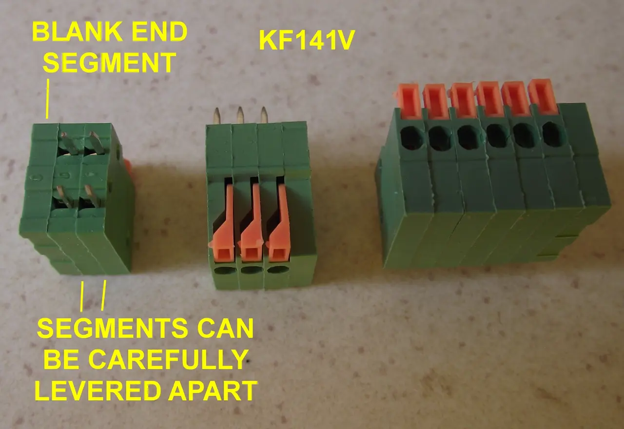
Caveat. These files have been retrieved from an archive - be aware of possible minor differences as the layout evolved, The KF141 connectors are modular wire push to 0.1" matrix pins. They can be bought in standard connection sizes or carefully split/reassembled for a custom one. The module also...
Licencia
Uso comercial permitidoCC BY-SA 4.0 — Atribución, compartir igual
Puedes usarlo y modificarlo dando crédito; las versiones modificadas deben compartirse con la misma licencia.
Al descargar aceptas respetar la licencia y dar crédito a Kris Sculptor.
Archivos (30)
- IR_LED_2_pin_connector_2.skp SKP · 193 KB
- IR_LED_2_pin_connector_2.stl STL · 16 KB
- Points_3_pin_connector_8.skp SKP · 228 KB
- Points_3_pin_connector_8.stl STL · 41 KB
- Signal_4_pin_connector_1.skp SKP · 197 KB
- Signal_4_pin_connector_1.stl STL · 17 KB
- Signal_5_pin_connector_13.skp SKP · 214 KB
- Signal_5_pin_connector_13.stl STL · 29 KB
- Signal_6_pin_connector_5.skp SKP · 202 KB
- Signal_6_pin_connector_5.stl STL · 24 KB
- Signal_7_pin_connector_7.skp SKP · 223 KB
- Signal_7_pin_connector_7.stl STL · 31 KB
- SPI_Screen_8_pin_connector_1.skp SKP · 220 KB
- SPI_Screen_8_pin_connector_1.stl STL · 31 KB
- Connector_2_pin_clip_mount_3.skp SKP · 196 KB
- Connector_2_pin_clip_mount_3.stl STL · 16 KB
- Connector_3_pin_clip_mount_5.skp SKP · 197 KB
- Connector_3_pin_clip_mount_5.stl STL · 24 KB
- Connector_4_pin_clip_mount_3.skp SKP · 196 KB
- Connector_4_pin_clip_mount_3.stl STL · 16 KB
- Connector_5_pin_clip_mount_3.skp SKP · 198 KB
- Connector_5_pin_clip_mount_3.stl STL · 16 KB
- Connector_6_pin_clip_mount_4.skp SKP · 191 KB
- Connector_6_pin_clip_mount_4.stl STL · 16 KB
- Connector_7_pin_clip_mount.skp SKP · 191 KB
- Connector_7_pin_clip_mount.stl STL · 17 KB
- Connector_8_pin_clip_mount.skp SKP · 195 KB
- Connector_8_pin_clip_mount.stl STL · 17 KB
- 5_pin_connector_end_stop.skp SKP · 188 KB
- 5_pin_connector_end_stop.stl STL · 11 KB
- Categoría
- Tecnología
- Formatos
- SKP, STL
- Descargas
- 0
- Publicado
Sobre este modelo
Caveat. These files have been retrieved from an archive - be aware of possible minor differences as the layout evolved, The KF141 connectors are modular wire push to 0.1" matrix pins. They can be bought in standard connection sizes or carefully split/reassembled for a custom one. The module also has a blank end segment. The wire holes may need a gentle reaming with a compass point to remove any flashing. The individual push-in wires need about 5mm of bare end. A small screwdriver blade helps to depress each retaining lever as the wire is pushed home. Designs exist elsewhere to use a bare 0.1" matrix board to mount a KF141R (right-angle) connector and attach a multiway cable with a cable tie. This design is for a 3D printed shroud for a KF141V (vertical) connector - with a matching clip for attaching it to a surface when wired. The multiway cable is secured with a cable tie and should be soldered to alternate top/bottom pins to minimise the risk of a short. eSun white PLA+ was used so that coloured CD fine pens can annotate the shroud function and wire positions. The printer was a Mingda Magician X with its standard hot end (0.4??). CURA usually was set to at least 80% density. ***The shroud's plate position must be on its "tail" to only leave support flashings on the cable entry end. Plate adhesion may need care. Some tuning may be needed to make the "click" fit optimal. Also the cable hole diameter may need adjustment so that a thin cable tie stops it moving or rotating. At least one needs the end stop printing then adding with glue. Sketchup tends to be very unpredictable if you try amending the .skp. A clip may bind initially - but a few strokes of the shroud should smooth the surfaces. To remove a module from the shroud - see picture using a small flat blade screwdriver to ease it past its "click" detent ridge.
Descripción original del autor, publicada en Thingiverse.