Remote Control Tank Drive
por Jackson Farhat en Printables
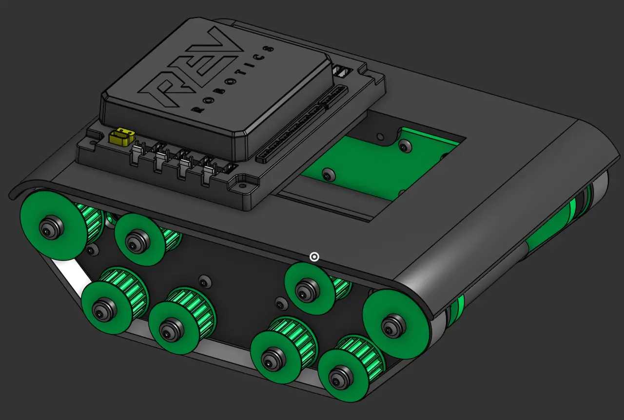
This drive functions on 2 GoBilda Bare Motors and a REV Hub.
Licencia
Uso comercial permitidoPuedes imprimirlo, modificarlo y venderlo dando crédito al autor.
Al descargar aceptas respetar la licencia y dar crédito a Jackson Farhat.
Archivos (17)
- Top Plate.step STEP · 82 KB
- Outer Plate.step STEP · 46 KB
- Internal Bar.step STEP · 52 KB
- Inner Plate.step STEP · 65 KB
- Internal Bar.step STEP · 52 KB
- Motor Mount.step STEP · 63 KB
- 3mm Spacer.step STEP · 6 KB
- 7mm Spacer.step STEP · 6 KB
- 18T 5M Pulley.stl STL · 169 KB
- 24T 5M Pulley.stl STL · 214 KB
- Inner Plate.stl STL · 515 KB
- Internal Bar.stl STL · 124 KB
- Top Plate.stl STL · 242 KB
- Outer Plate.stl STL · 307 KB
- Motor Mount.stl STL · 169 KB
- 3mm Spacer.stl STL · 23 KB
- 7mm Spacer.stl STL · 23 KB
- Categoría
- Varios
- Formatos
- STEP, STL
- Descargas
- 3
- Publicado
Sobre este modelo
I was inspired by some really cool designs at Open Sauce this year and decided that I wanted to join the people with custom RC Vehicles and settled on this tank drive. I used the GoBilda Motors because I have them, but you can realistically use any ones you want. The goal is that it will be fast which is why I chose Bare Motors. It is more meant to function as an RC Car and probably can't hold a whole lot.
This model was made to function as a little tank that you can drive around. It runs on 2 GoBilda Bare Motors and a 112 tooth HTD5 belt that is 15mm wide for the tread.
Materials: - 2*Inner Plate - 2*Outer Plate - 1*Internal Bar - 1*Top Plate - 2*Motor Mount - 18*Each Spacer Included - 4*24 Tooth Pulley - 6*18 Tooth Pulley - 2*112T HT5 15mm Width Timing Belt - 1*REV Control Hub (Or other DC Motor Control System) - 1*Battery - 2*GoBilda Bare Motors - 2*GoBilda 36T Slip Gear - 2*Gobilda 24T Slip Gear - 36*8mm ID 14mm OD Bearings - 18*48mm Gobilda Axles - 10*8mm GoBilda Standoffs (I included a STL file so u don't have to buy them) - Screws and Hardware In order to assemble the Tank Drive, you will need to follow these steps:
1. Attach each of your Bare Motors to a Motor Mount 2. Take the two inner plates and attach one motor two each plate in this orientation (the plates have counterbores on one side, make sure the motor is mounted on the opposite side of the counterbored holes):
3. Screw 6 8mm Standoffs into the locations marked by yellow indicators on each side panel (They should be sticking out opposite of the motor)
4. Place Bearings inside of every slot on the the Inner and Outer Plates. The flange should be placed inside the small recesses on the Outer Plates and facing out on the Inner Plates. (The picture shows the recess on the Outer Plate).
5. Take the Internal Bar and screw M4 screws through the Inner Plate into the Bar (holes are marked by yellow)
6. Screw the Top Plate on through the four counterbored holes:
7. Insert all of your 48mm Axles into the bearings on the inner plates (Be sure that the C-Clip is inside the chassis)
8. Slide the 7mm Spacers over every single Axle except the ones on the motor and directly next to the motor. On those, insert the 24T Slip Gear on the Motor Axle and the 36T Slip Gear on the axle directly adjacent. (The motor is the yellow outline).
9. Now slide the coinciding bearings on the Outer plate over the axles connected to the Inner Plate, then screw in the Outer Plate to the standoffs you put on the Inner Plate. You should get a plate sandwich that looks like this or one that has the black gears on the other side (you should have both, one for right, one for left):
10. Now it is time to put the pulleys on, the large Pulleys in the picture are the 24T ones and the smaller ones are 18T. On the final pulley on each side (it doesn't matter which), place the 112T HTD5 Belt over all of the ones already on, then on the one you are about to put on, then slide the final pulley on. After doing that, slide the 3mm spacers onto the shaft and screw a screw with a small shim on it to lock the axle and pulley in place. (First Picture is pulleys, second is Spacer -> Shim that has an ID < 8 -> Screw, the yellow is the axle)
11. Mount the REV Hub on the Top Plate with four screws:
Descripción original del autor, publicada en Printables.