Rack fit test 1U for 10″ and 19″ racks – ear, M3 joint and tolerance comb (free)
por Magmacode en Thingiverse
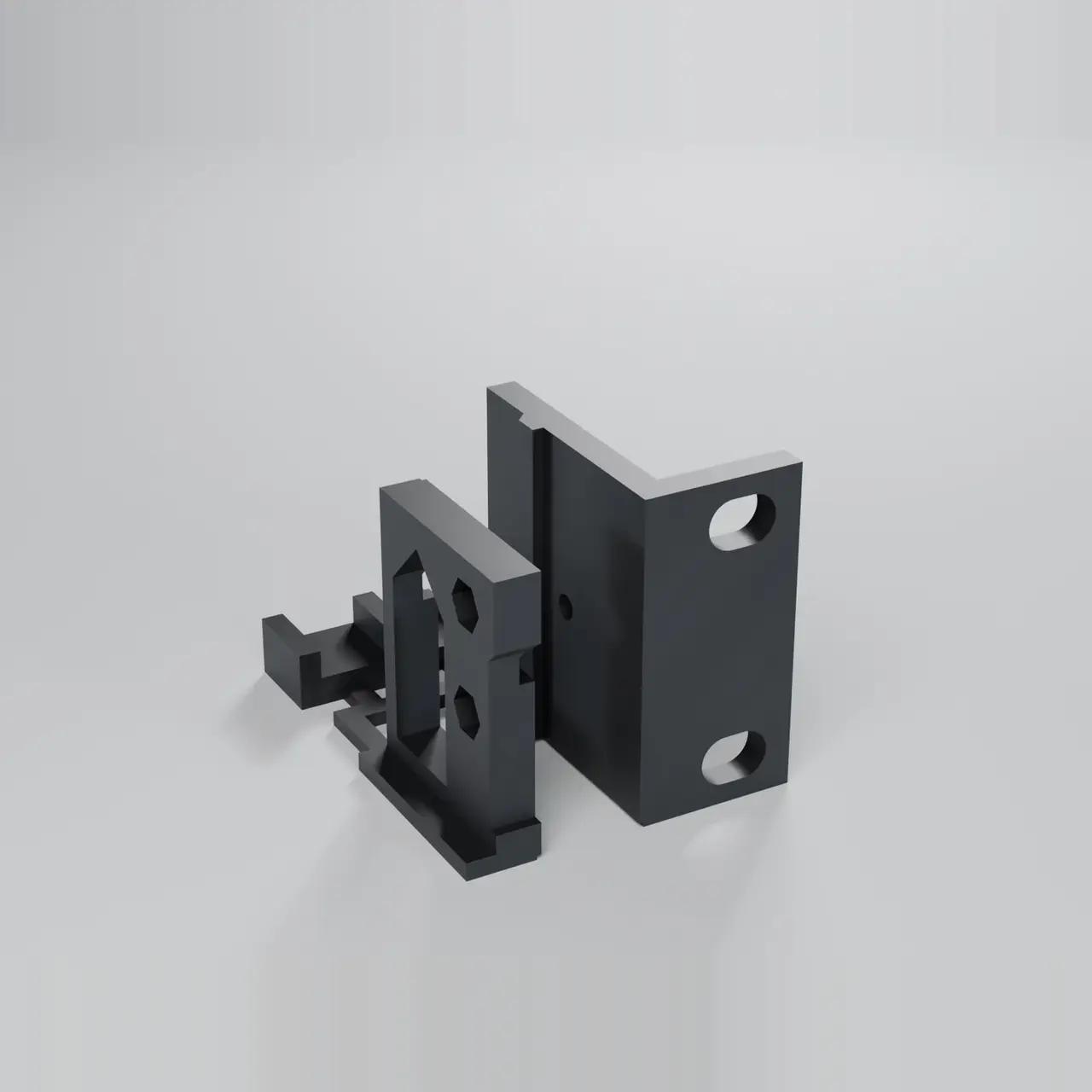
A real 1U rack ear, a piece of device carrier with the M3 joint and a tolerance comb: check rack and printer before printing the full insert. Fits: 10″ racks (slot for 234.0–239.5 mm hole spacing) and 19″ racks (465.1 ± 1 mm); the same hole width and height for both. Our rack inserts consist of a...
Licencia
Uso comercial permitidoPuedes imprimirlo, modificarlo y venderlo dando crédito al autor.
Al descargar aceptas respetar la licencia y dar crédito a Magmacode.
Archivos (5)
- Categoría
- Para tu impresora
- Formatos
- STL, 3MF, STEP, TXT
- Descargas
- 0
- Publicado
Sobre este modelo
A real 1U rack ear, a piece of device carrier with the M3 joint and a tolerance comb: check rack and printer before printing the full insert. Fits: 10″ racks (slot for 234.0–239.5 mm hole spacing) and 19″ racks (465.1 ± 1 mm); the same hole width and height for both. Our rack inserts consist of a device carrier and two rack ears. This free part contains exactly that joint in a small format, so you can check before the big print: - 1U ear with slot (6.5 mm high): screw it to a rail. Does your screw fit (#10-32, M5 or M6), does the plate sit within one unit without touching the next one? - Carrier piece with the M3 joint: bolt the ear on with 2 × M3×10 countersunk screws and nuts. Do the nuts go into their pockets, are the fronts flush? - Tolerance comb: snap off the 10 mm tongue and try it in the three slots (+0.3 / +0.5 / +0.7 mm, 1–3 notches). Our joint uses +0.5 mm.
Hole spacing: there is no standard for 10-inch racks. We found 235 to 238 mm centre to centre; our 10″ ears have slots for 234.0 to 239.5 mm. Measure the hole centres on your rack if in doubt. 19″ ears: 465.1 ± 1 mm per EIA-310. Hole width and height are the same for 10″ and 19″, so one test part covers both. The dimensions come from standard tables, manufacturer data and community measurements; our part has not been tested on a rack yet. That is exactly what this test part is for. Load of the inserts: without rear support (2-post rack) 1 kg at most, with the rear support brackets (4-post rack) 2 kg at most, both guide values, not a tested load rating. The test part itself carries no device. Print settings - Material: PETG (or ASA), ideally the material of your later insert. - Layer height 0.2 mm, 3 walls, 15 % infill, no supports. - Orientation: As the file is laid out: ear upright, carrier piece front face down (like the real carrier), comb and tongue flat. - Print time approx. 1 h 09 min, about 18 g.
Hardware (not included) - 2 × M3×10 countersunk screw (ISO 10642) - 2 × M3 nut (ISO 4032) - 1 × your rack's screw with a washer
Assembly - Snap the parts off the bars and deburr. - Screw the ear to one rail with a rack screw and washer; check the height against the next unit. - Press the M3 nuts into the pockets of the carrier piece from inside, fit the ear (tongue into groove) and fasten with 2 × M3×10 countersunk screws. - Try the tongue in the three comb slots: the one that fits without force and without play shows your printer's clearance.
Safety For checking the fit only; do not hang anything from it. Fit 10″ slot covers 234.0–239.5 mm centre to centre, 19″ 464.1–466.1 mm. FAQ Which screws do I need? For the rack, your rack's screws (#10-32, M5 or M6) with a washer, because the head is only slightly larger than the slot. For the joint, 2 × M3×10 countersunk (ISO 10642) and 2 M3 nuts. How it's made Parametric CAD (build123d, Python), exact solids. The CAD code was written with an AI assistant and checked by us; no AI-generated meshes or images. Renders are made from the CAD in Blender; they are not photos. License CC BY 4.0: free to use, also commercially; credit Magmacode when you share it or derivatives. Matching rack inserts for Mac mini, mini PCs, Raspberry Pi, UniFi gear and switches are in the Magmacode profile.
Descripción original del autor, publicada en Thingiverse.