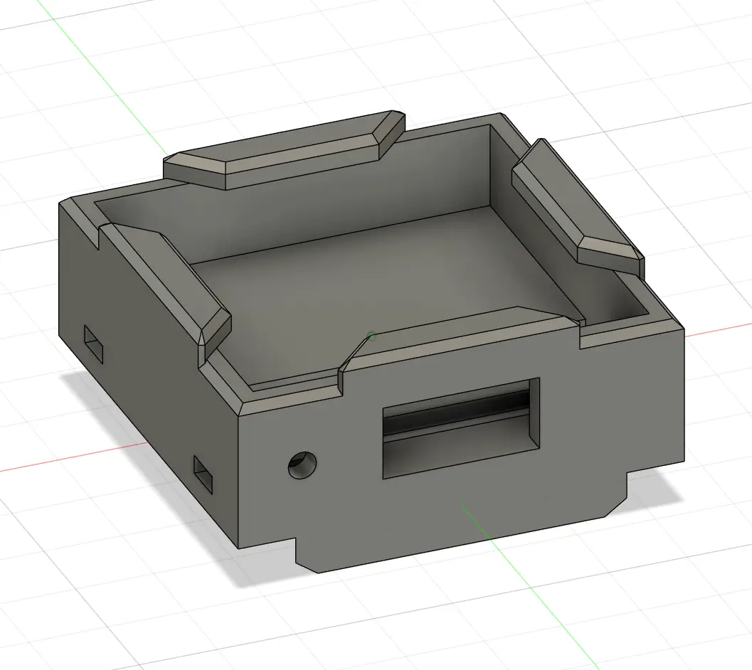
Pavo20 GPS Mount
por Duane Degn en Printables
Mount to attach a GPS (Flywoo GOKU GM10 Pro V3 w/ Compass) to a Pavo20 Pro II (4S).
Licencia
Uso comercial permitidoPuedes imprimirlo, modificarlo y venderlo dando crédito al autor.
Al descargar aceptas respetar la licencia y dar crédito a Duane Degn.
Archivos (1)
- Categoría
- Varios
- Formatos
- STL
- Descargas
- 0
- Publicado
Sobre este modelo
A mount used to attach the Flywoo GOKU GM10 Pro V3 GPS w/ Compass to a BetaFPV Pavo20 Pro II quadcopter. The compass is easiest to use on the 4S version of the Pavo20 since the 4S PCB has a working I2C bus. The GPS can be used without the compass but I prefer using a compass on my RC aircraft. This mount has recesses which align with the features on top of the Pavo20 Pro frame for the O4 transmitter. I found the best orientation when printing what to place the model on its front corner and let the automated supports support the bottom features. This orientation allows the top section to print without supports.
The mount is attached to the top of the Pavo20 using zip ties. I had to use four zip ties since the ones I had weren't long enough to only two. I used about 3mm of clear TPU as a light pipe to bring the light from the LEDs to the outside of the mount. The light pipe worked really well on my build. I used a square of copper tape under the GPS unit to shield it from interference. I added a layer of Kapton tape on top of the copper tape to prevent shorts. The order things are installed is important. - Use zip ties to secure the mount. I positioned the zip tie latches so they were at the bottom of the O4 transmitter. The next step requires the zip ties to be in their final position.
- Add a square of copper tape (with Kapton layer). The copper tape is applied directly to one of the zip ties.
- Add light pipe of clear filament. I used clear TPU, Any clear filament should work. Have the filament extend inside the mount about 1.5 mm past the internal wall. Make sure the clear filament is positioned above the copper tape.
- Glue (or melt) the light pipe in place. I used E6000 glue.
- Cut the light pipe flush with the front of the mount.
- Feed the GPS connector through the front opening of the mount.
- Press the GPS unit into position while pulling the wires trough the front opening. Make sure the wires don't get pinched.
- Tuck extra wire between the O4 camera and the O4 transmitter.
Descripción original del autor, publicada en Printables.