manual, mechanical pen plotter
por andrei en Printables
manual, knob and slider driven pen plotter using rubber bands. made for 3d printer/laser cutter design practice!
Licencia
Uso comercial permitidoPuedes imprimirlo, modificarlo y venderlo sin pedir permiso ni dar crédito.
Al descargar aceptas respetar la licencia y dar crédito a andrei.
Archivos (12)
- pen collar right.step STEP · 25 KB
- slider.step STEP · 15 KB
- pen collar top.step STEP · 8 KB
- top collar.step STEP · 76 KB
- platform top.step STEP · 59 KB
- bottom collar.step STEP · 76 KB
- platformbottom.step STEP · 794 KB
- pen collar left.step STEP · 25 KB
- knob.step STEP · 360 KB
- pulley.step STEP · 9 KB
- screw gear.step STEP · 1,2 MB
- knob gear.step STEP · 1,2 MB
- Categoría
- Para tu impresora
- Formatos
- STEP
- Descargas
- 0
- Publicado
Sobre este modelo
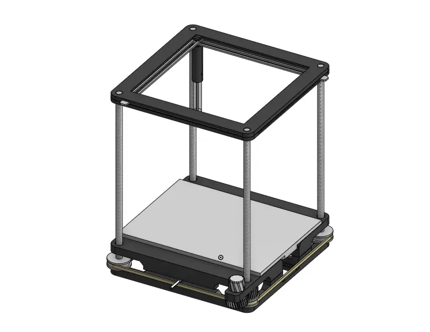
overview : this project is a pen plotter that is fully mechanically driven, using lead screws for the z-axis and 3d printed sliders to move a pen in both the x and y directions. i came up with the idea because i'm really into cars and mechanical engineering - so modelling something mechanically and kinematically complex like a pen plotter in 3d space seemed like a cool little learning experience. why a pen plotter? : my goal in the future is to design and manufacture automotive systems for formula 1 cars, so the kinematics research, mating CAD assemblies and designing for manufacturing are extremely valuable skills to learn! learning about the way 3d printers and pen plotters move, using lead screws and the xy gantries used here also helped me learn how to possibly design a custom 3d printer/pen plotter in the future. function & how to use : the function of the project is to accurately draw wherever the user moves it, with varying levels of adjustability. to higher and lower the pen, use the knob at the front to rotate the lead screws and move the pen. to move the pen in the x and y directions, use the sliders on the gantry and it will move! overall dimensions : 200.00 x 200.00 x 252.00 note: this is NOT print in place, so each individual part will fit in a 256mm^3 build volume, but the entire build IS bigger than 256mm^3 :)
model build requirements : 1 x knob 1 x knob gear 1 x platform bottom 1 x platform top 1 x screw gear 4 x 250mm t8 lead screws 4 x pulleys 2 x sliders 1 x top collar 1 x bottom collar 1 x rubber band 1 x pen collar left 1 x pen collar right 1 x pen collar top 1 x m3 thumbscrew model build instructions : position the pulleys over the holes in each corner of the platform's bottom, then thread the t8 lead screw through the pulley to the bottom of the platform, ensuring each lead screw spins properly. stretch the rubber band over all 4 of the pulleys so that when one spins, they all spin. friction fit the screw gear on the lead screw closest to the little outwards extrusion on the where the top platform is going to be. glue the top part of the platform to bottom. position the knob through the hole in the outwards extrusion and glue the knob gear on the other side, making sure it meshes with the screw gear. position one of the sliders through the slot of the bottom collar. position one of the sliders through the slot of the top collar. glue the top and bottom collar together. glue both halves of the pen collar together. position the pen collar through both sliders and glue the pen collar top to the pen collar. thread the collar on to the lead screws using the knob.
Descripción original del autor, publicada en Printables.