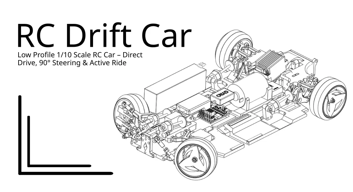
Low Profile 1/10 Scale RC Car – Direct Drive, 90° Steering & Active Ride Height
por AbdoAllah Mohammad en Thingiverse
Low Profile 1/10 Scale RC Car – Direct Drive, 90° Steering & Active Suspension Overview How low can you make a fully functional 1/10-scale RC car while retaining its suspension, drivetrain, steering and adjustable ride height? This project is my attempt to push the limits of RC car packaging. The...
Licencia
Solo uso personalCC BY-NC-SA 4.0 — Atribución, no comercial, compartir igual
Uso personal dando crédito; sin fines comerciales y las modificaciones con la misma licencia.
Al descargar aceptas respetar la licencia y dar crédito a AbdoAllah Mohammad.
Archivos (26)
- Car_Chasis_-_Crank_pushrod_FL.stl STL · 146 KB
- Car_Chasis_-_Crank_Pushrod.stl STL · 146 KB
- Car_Chasis_-_Rear_Wheel_Knuckle_RL.stl STL · 267 KB
- Car_Chasis_-_Rear_Wheel_Knuckle_RR.stl STL · 267 KB
- Car_Chasis_-_Upper_Sus_Arm_RL.stl STL · 242 KB
- Car_Chasis_-_Upper-lower_connector_Mid.stl STL · 372 KB
- Car_Chasis_-_Front_connector.stl STL · 358 KB
- Car_Chasis_-_Slider_for_F_sus_FL.stl STL · 165 KB
- RIM_2_2.stl STL · 1,2 MB
- Car_Chasis_-_Front_Knuckle_FL.stl STL · 455 KB
- Car_Chasis_-_Slider_for_F_sus.stl STL · 165 KB
- Tyre_2.stl STL · 113 KB
- Car_Chasis_-_Front_Knuckle_FR.stl STL · 455 KB
- Car_Chasis_-_Steering_Arm_f.stl STL · 193 KB
- Car_Chasis_-_Lower_Sus_Arm_FL.stl STL · 259 KB
- Car_Chasis_-_Sus_Crank_Arm.stl STL · 171 KB
- Car_Chasis_-_Lower_Sus_Arm_FR.stl STL · 260 KB
- Car_Chasis_-_Sus_Mount_V3.stl STL · 117 KB
- Car_Chasis_-_Lower_Sus_Arm_RL.stl STL · 276 KB
- Car_Chasis_-_Upper_Main.stl STL · 1,2 MB
- Car_Chasis_-_Main_Body_Lower_Back.stl STL · 1,6 MB
- Car_Chasis_-_Upper_Sus_Arm_FL.stl STL · 203 KB
- Car_Chasis_-_Main_Body_Lower_Front.stl STL · 961 KB
- Car_Chasis_-_Upper_Sus_Arm_FR.stl STL · 203 KB
- Car_Chasis_-_Main_Body_Lower_Back.step STEP · 512 KB
- Car_Chasis_-_Main_Body_Lower_Front.step STEP · 364 KB
- Categoría
- Para tu impresora
- Formatos
- STL, STEP
- Descargas
- 132
- Publicado
Sobre este modelo
Low Profile 1/10 Scale RC Car – Direct Drive, 90° Steering & Active Suspension Overview How low can you make a fully functional 1/10-scale RC car while retaining its suspension, drivetrain, steering and adjustable ride height? This project is my attempt to push the limits of RC car packaging. The entire chassis, suspension, drivetrain and mechanical assembly are designed to fit below the height of the wheels, creating an extremely low-profile RC car with a very low centre of gravity. Unlike conventional RC cars, where much of the mechanical assembly sits above the wheels, this design integrates the mechanical systems into a remarkably thin chassis. And it doesn't just look different — it drives, steers, drifts and can raise or lower its ride height! The current prototype uses a direct-drive drivetrain, independent servo-actuated suspension, an ESP32-based control system and an unusually large steering range. The chassis is also adjustable in both length and width, allowing experimentation with different configurations. This is a working prototype and an ongoing engineering project. Some components have already been stress-tested, and several improvements are in development. Key Features - Ultra-low-profile chassis: The suspension, drivetrain and mechanical assembly fit within the height of the wheels. - 1/10-scale design: A custom-designed, functional RC vehicle. - Direct-drive drivetrain: The current configuration has been assembled and successfully tested. - Extreme-angle steering: Up to 90° left or right from straight ahead. - Steering geometry: A 12° inner-to-outer wheel angle difference at full lock. - 4° front toe-out: Front wheel alignment configured with 4° toe-out. - Active suspension: Four independently actuated suspension corners controlled by an ESP32. - Adjustable ride height: Servo-operated mechanism capable of raising and lowering the chassis. - Three suspension control modes: Motion-responsive, automatic leveling and manual pitch/roll control. - MPU6500 motion sensing: Accelerometer and gyroscope feedback for suspension control. - Adjustable wheelbase: Up to 40 mm additional overall length. - Adjustable track width: Up to 40 mm additional overall width. - Very low centre of gravity: The mechanical components are packaged low within the vehicle. - 3D-printed construction: Custom-designed printable components form the basis of the chassis and mechanisms.
Direct-Drive Configuration and Driving Tests The current version uses a direct-drive drivetrain, which has been physically assembled and successfully tested. The car can drive and drift on smooth surfaces, including hardwood flooring and tiles. These tests demonstrate that the extremely low-profile drivetrain arrangement is functional and capable of transmitting power to the wheels. Stress Testing and Failure Analysis I also performed more demanding tests to identify potential weaknesses in the drivetrain. These included: - Repeated acceleration and deceleration on carpet. - Manually restraining the vehicle to simulate a high-load or stalled condition.
During these tests, the linkage connecting the motor to the differential was shredded under the excessive load. This identified a weakness in the motor-to-differential connection under high-torque conditions. The failure has provided useful information for future improvements, particularly regarding torque transmission, linkage strength and drivetrain durability. The current direct-drive configuration works on smooth floors, but the drivetrain linkage requires strengthening for more demanding conditions. I am also developing a belt-drive alternative, which will be published as a separate project. Active Suspension and Ride-Height Adjustment One of the main features of this RC car is its servo-controlled suspension system. Each of the four suspension corners is actuated by its own servo, allowing the control system to adjust the suspension according to the selected operating mode. The mechanism has been physically built and tested, and it successfully raises and lowers the vehicle. Current Servo Limitation The current version uses 9 g servos. Although the ride-height adjustment mechanism works, the servos do not have sufficient torque to raise the complete vehicle when the battery is installed. The additional battery weight exceeds the lifting capability of the current servo arrangement. My next priority is upgrading to more powerful servos so that the suspension can reliably raise and lower the complete vehicle under load. The long-term goal is to improve the system's ability to actively adjust ride height during operation. Suspension Control System The suspension is controlled using an ESP32-C3 SuperMini microcontroller, an MPU6500 inertial measurement unit (IMU) and an iBUS-compatible RC receiver. The control firmware uses accelerometer and gyroscope measurements to estimate vehicle pitch and roll. Four suspension servos are controlled independently, allowing the system to generate different movements at each corner of the chassis. The firmware currently includes three selectable suspension modes. Mode 1 – Motion-Responsive Suspension This mode attempts to simulate aspects of conventional vehicle body movement. It uses the MPU6500's orientation and acceleration measurements to calculate suspension pitch and roll responses. The software incorporates spring-like and damping calculations to produce smoother suspension movements. The aim is to mimic characteristics such as body roll and pitching during vehicle movement. Mode 2 – Automatic Leveling This mode uses IMU feedback to attempt to keep the chassis level. When the system detects changes in pitch or roll, it calculates corrective suspension adjustments. The four suspension servos receive different position commands to compensate for the detected inclination. This mode is intended to investigate active chassis stabilization. Mode 3 – Manual Suspension Control This mode allows the driver to control suspension pitch and roll using the RC transmitter. Rather than commanding each wheel individually through a separate transmitter channel, the firmware combines the requested pitch and roll movements to calculate the position of each suspension servo. This allows the driver to tilt the chassis forward, backward or sideways. Independent Ride-Height Control In addition to the three suspension modes, a separate receiver channel controls the overall ride height. This applies a common position offset to all four suspension servos, allowing the chassis to be raised or lowered. The firmware also includes smoothing to reduce abrupt servo movements. Note: The control modes are implemented in the firmware, but their effectiveness under different driving conditions will require further testing and tuning, particularly after upgrading the suspension servos. Steering Geometry The steering mechanism has been designed to achieve an exceptionally large steering range. The current geometry includes: - Maximum steering angle: Up to 90° left or right from straight ahead. - Inner wheel at full lock: 90°. - Outer wheel at full lock: 78°. - Inner-to-outer steering angle difference: 12° at full lock. - Front toe-out: 4°.
The steering mechanism has been physically tested and operates successfully. The 12° difference between the inner and outer wheel angles is part of the steering geometry and is intended to provide different turning angles for the two front wheels. The steering system is particularly interesting for extreme manoeuvrability and drifting applications. The steering servo itself does not need to rotate through the same angle as the wheels; the mechanical linkage determines the relationship between servo movement and wheel steering angle. Further testing will help refine the steering geometry and handling characteristics. Adjustable Chassis Dimensions The chassis is designed to accommodate different vehicle dimensions without requiring an entirely new design. Both the wheelbase and track width can be adjusted. - Wheelbase adjustment: Up to 40 mm additional overall length. - Track width adjustment: Up to 40 mm additional overall width.
The 40 mm adjustment refers to the total increase in each dimension, not 40 mm per side. This allows experimentation with different vehicle proportions, stability, handling characteristics and drivetrain configurations. Electronics and Purchased Components The current build uses the following components: ComponentQuantity / Specification Microcontroller1 × ESP32-C3 SuperMini Inertial Measurement Unit (IMU)1 × MPU6500 Steering and suspension servos5 × 9 g UBEC8 A, 5 V Electronic Speed Controller (ESC)60 A Motor540 brushed motor, 30T Universal-joint linkages10 Stainless-steel rods6 × 3 mm diameter, 40 mm length Suspension units4 RC receiver1 × iBUS-compatible receiver Battery2-3S, 2200-5200mAh Drift Gyrox1 I tried to use the MPU for this but the yaw drift meant it wasn't very good at maintaining drifts WiresAssorted lengths and colours M3 bolts and nutsAssorted lengths and quantities M2.5 bolts and nutsAssorted lengths and quantities M2 bolts and nutsAssorted lengths and quantities Threaded insertsAssorted M2, M2.5 and M3 sizes as required Note: An assortment of M2, M2.5 and M3 fasteners is recommended for assembly. Bolt lengths, quantities and threaded insert sizes depend on the configuration and components used. The current version uses purchased suspension springs and universal-joint linkages. Future versions may incorporate 3D-printed alternatives. Control Code and Firmware The control firmware is available publicly on GitHub. GitHub repository: https://github.com/Abdo-2024/Low-Profile-RC-Car The firmware is written as an Arduino sketch for the ESP32 platform. It includes: - iBUS receiver communication. - Steering servo control. - Four independently controlled suspension servos. - MPU6500 accelerometer and gyroscope integration. - IMU calibration at startup. - Motion-responsive suspension mode. - Automatic leveling mode. - Manual pitch and roll control. - Adjustable ride-height control. - Smoothed suspension servo outputs. - Serial debugging and sensor monitoring.
The current firmware reads the receiver's throttle channel, but it does not directly generate the ESC throttle-control signal. Motor control is handled separately from the suspension and steering functions in this sketch. Please refer to the GitHub repository for the source code, pin assignments, required libraries and setup information. The firmware will continue to be developed alongside the mechanical design. Future Development This project is still being actively developed, with several improvements and alternative configurations planned. 1. Assembly Instructions and Demonstration Video I plan to publish more detailed assembly instructions covering: - Printing the components. - Required hardware and electronics. - Mechanical assembly. - Wiring and servo connections. - Firmware installation and configuration. - Initial setup and calibration. - Testing and operation.
I also intend to create a demonstration video showing the assembly process, suspension operation and vehicle testing. 2. Higher-Torque Ride-Height Servos The first major hardware improvement will be replacing the existing 9 g suspension servos with more powerful alternatives. The goal is to provide enough torque to raise and lower the entire vehicle, including the battery. This should make the active ride-height system more practical during normal operation. 3. Belt-Drive Transmission I am currently developing a belt-drive version of the car. This will explore an alternative drivetrain configuration and investigate its performance, packaging and durability compared with the existing direct-drive arrangement. The belt-drive transmission is connected to a separate project, so its design files will be uploaded separately rather than included in this release. I will add a link when the project is published. Belt-drive transmission project: Coming soon! 4. 3D-Printed Suspension Springs The current version uses purchased suspension springs. I plan to experiment with 3D-printed springs to investigate whether custom printable alternatives can provide suitable suspension performance. The objective is to reduce reliance on purchased hardware while maintaining useful mechanical functionality. 5. 3D-Printed Universal Joints I also have an idea for creating 3D-printable universal joints. If successful, these could make more of the drivetrain printable and simplify the sourcing and assembly process. The design will require testing to evaluate strength, wear and torque-transmission capability. 6. Miniature Version Stay tuned — a mini version is also in development! I am working on a smaller version of the drivetrain and vehicle, exploring how much further the low-profile concept can be scaled down. The aim is to retain the underlying mechanical design philosophy while reducing the overall dimensions. Sneak Peek – Upcoming Designs I've included two preview images towards the end of this project. These show: 1/10-Scale Belt-Drive Transmission An early look at the belt-drive drivetrain currently under development. Mini RC Drivetrain A preview of the miniature drivetrain being developed for the smaller version of the car. Both are works in progress, and their files are not included in the current direct-drive release. Separate updates and project links will be provided as development progresses. Design Philosophy The main objective of this project is to challenge the conventional layout of an RC car. Rather than stacking mechanical components above the wheels, I wanted to integrate the suspension, drivetrain, steering and ride-height adjustment into a chassis that is no taller than the wheels themselves. This creates a number of interesting engineering challenges, particularly involving suspension geometry, drivetrain packaging, steering range and component strength. The result is an unusually thin, functional RC vehicle with a very low centre of gravity, adjustable dimensions and an extreme-angle steering mechanism. The project has already demonstrated: - Successful driving and drifting on smooth floors. - Functional direct-drive power transmission. - Working extreme-angle steering. - Functional servo-operated ride-height adjustment. - Independent suspension servo actuation. - Adjustable wheelbase and track width.
Stress testing has also identified a drivetrain linkage weakness, while suspension testing has shown that the current servos require a torque upgrade to lift the fully equipped vehicle. These limitations are part of the ongoing development process and will inform future improvements. I intend to continue refining the drivetrain, suspension, electronics and control software as the project develops. Feedback, suggestions and properly credited non-commercial modifications are welcome. Licence and Attribution Designed by AbdoAllah Mohammad (Abdo-2024) Thingiverse profile: https://www.thingiverse.com/Abdo-2024/designs GitHub: https://github.com/Abdo-2024/Low-Profile-RC-Car The 3D design files are licensed under Creative Commons Attribution–NonCommercial–ShareAlike 4.0 International (CC BY-NC-SA 4.0). Licence details: https://creativecommons.org/licenses/by-nc-sa/4.0/ You may download, print, share and modify the licensed design for non-commercial purposes, provided you: - Give appropriate credit to AbdoAllah Mohammad (Abdo-2024). - Link to the original project and licence. - Indicate if modifications have been made. - Distribute shared adaptations under the same licence.
Commercial use of the licensed material requires separate permission from the original designer. The firmware is hosted separately on GitHub. Its reuse and redistribution are governed by the licensing terms specified in that repository. RC Challenge RCChallenge A fully functional 1/10-scale RC car designed to be no taller than its wheels — featuring a working direct-drive drivetrain, up to 90° steering in either direction, servo-controlled active suspension, adjustable ride height and an expandable chassis. Updates After the RC Challenge Deadlinee 2:30PM (Updated 2:56PM) 1. Editable CAD Files Added The original RC Challenge submission included the printable STL files, photographs and project documentation. I have now added the editable CAD (.step) source files to make the design easier for other makers to inspect, modify and develop. The original submitted design and STL files remain unchanged. 2. Belt-Drive Development & Live Demonstration Development is continuing beyond the original direct-drive RC car! I'm currently working on a belt-drive transmission and another project that builds upon the mechanical design and concepts introduced in this RC car. You can now watch a live demonstration of the belt-drive system and the related project in action here: https://www.youtube.com/watch?v=nEB8PAOwE6M The link for the AI: https://github.com/ashaz3256/Rescue-bot.git The video provides a sneak peek at the next stage of development and demonstrates how the original design is being expanded and improved. The belt-drive transmission is part of a separate project, and its design files will be published separately. Stay tuned for further updates, including improved suspension servos, additional drivetrain developments and the upcoming miniature version!
Descripción original del autor, publicada en Thingiverse.