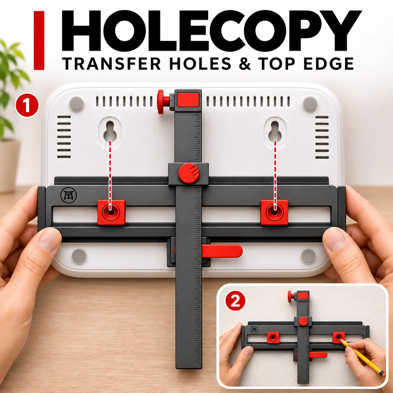
HOLECOPY — Hole and Top-Edge Transfer Jig
por Torii Creative Studio en Printables
Transfer two mounting holes and the top-edge position with one adjustable, fully printable jig.
Licencia
Solo uso personalCC BY-NC 4.0 — Atribución, no comercial
Puedes imprimirlo y modificarlo para uso personal dando crédito. No se permite vender las impresiones.
Al descargar aceptas respetar la licencia y dar crédito a Torii Creative Studio.
Archivos (18)
- HOLECOPY_V2.f3d F3D · 6,3 MB
- HOLECOPY_V2.step STEP · 4,5 MB
- C02_x1.stl STL · 12 KB
- C03_x1.stl STL · 49 KB
- C05_x2.stl STL · 30 KB
- C06_x2.stl STL · 81 KB
- C04_x1.stl STL · 62 KB
- C07L_x1.stl STL · 10 KB
- C07R_x1.stl STL · 14 KB
- C08_x1.stl STL · 336 KB
- C10_x3.stl STL · 1,5 MB
- T01_x1.stl STL · 12 KB
- C11_x1.stl STL · 7 KB
- C01_V2_x1.stl STL · 260 KB
- C09_V2_x1.stl STL · 295 KB
- HOLECOPY_V2_Instrukcja_PL.pdf PDF · 556 KB
- HOLECOPY_V2_Assembly_EN.pdf PDF · 553 KB
- HOLECOPY_V2_Print_Package.zip ZIP · 8,9 MB
- Categoría
- Herramientas
- Formatos
- F3D, STEP, STL, PDF, ZIP
- Descargas
- 45
- Publicado
Sobre este modelo
HOLECOPY helps you transfer the position of two mounting holes and the top edge of an object to a wall. Set both retractable tips in the mounting points, close the common cam lever, and adjust the sliding ruler against the top edge. Retract the tips and edge fence, place the jig flat against the wall, align the edge reference and mark the holes through the tips. FEATURES • Nominal marker spacing: 18–172 mm. • Nominal distance from hole centres to top edge: 35–145 mm. • 3.6 mm locating tips; a fine pencil is needed for marking. • Common cam lock, retractable markers and sliding top-edge reference. • All structural and moving parts are 3D printed. PRINT AND ASSEMBLY Print T01 plus one C05 and one C06 first to check sliding and retention. Reuse C05 and C06 in the finished tool. Quantities are included in the STL filenames. Recommended starting point: PETG, 0.4 mm nozzle, 0.2 mm layers, four perimeters and 30% infill; use five perimeters for the axle and snap parts. Inspect bridges and supports in your slicer. Assembly guides in English and Polish are included. FUSION The F3D and STEP files are included. The separate Fusion script positions the assembly; see the last page of the guide. VALIDATION The CAD geometry and selected mechanism positions have been checked digitally. Fit, locking, accuracy and support requirements have not been verified by a physical print or slicer test.
Descripción original del autor, publicada en Printables.