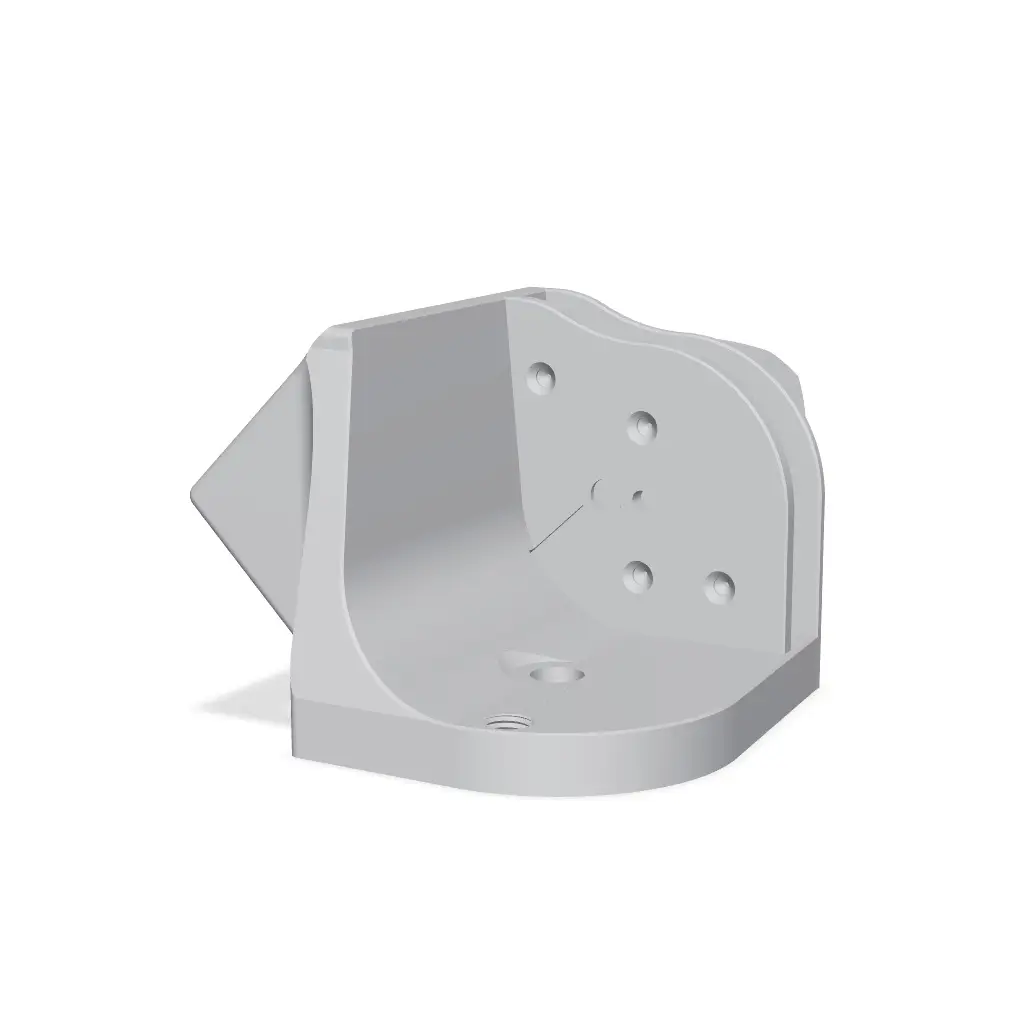
Hand Crank Spreader (Fully 3d Printable)
I've spent a ton of time trying to get this model perfected. I'm finally throwing in the towel though. It's at a stage where it's working but could be better. I didn't want all the time on this to be completely for nothing. Therefore, I'm posting it for free download so I can move on from this proje
Thangs entrega los archivos a usuarios con cuenta gratuita
Licencia
Solo uso personalSin licencia indicada
El autor no indicó una licencia: todos los derechos le pertenecen. Úsalo solo para imprimir en casa y consulta al autor para cualquier otro uso.
Al descargar aceptas respetar la licencia y dar crédito a Jake M.
Archivos (27)
- Hand Crank Spreader - Base - No Custom Support.stl STL · 6,9 MB
- Hand Crank Spreader - Base - With Custom Support.stl STL · 6,9 MB
- HCS - Agitator Paddle.stl STL · 89 KB
- HCS - Arm Rest Handle Lock.stl STL · 1,2 MB
- HCS - Arm Rest Lock Bolt.stl STL · 1,4 MB
- HCS - Arm Rest.stl STL · 2,1 MB
- HCS - Crank Arm.stl STL · 74 KB
- HCS - Gear Box Cover.stl STL · 302 KB
- HCS - Hopper secure bolt.stl STL · 340 KB
- HCS - Hopper.stl STL · 2,6 MB
- HCS - Inside Drive Shaft Nut.stl STL · 243 KB
- HCS - Knob Shaft Nut.stl STL · 166 KB
- HCS - Knob Shaft.stl STL · 321 KB
- HCS - Knob.stl STL · 84 KB
- HCS - Lower Gear Box Bolt.stl STL · 810 KB
- HCS - Lower Helical Gear Nut.stl STL · 180 KB
- HCS - Lower Helical Spur Gear.stl STL · 2,3 MB
- HCS - Main Drive Shaft.stl STL · 652 KB
- HCS - Main Drive Spur gear (48 teeth).stl STL · 769 KB
- HCS - Outer Drive Shaft Nut.stl STL · 246 KB
- HCS - Push Pull Gate.stl STL · 2,6 MB
- HCS - Thrower Disc.stl STL · 82 KB
- HCS - Thrower Shaft Nut.stl STL · 875 KB
- HCS - Thrower Shaft Spur gear (12 teeth).stl STL · 2,0 MB
- HCS - Upper Gear Box Bolt.stl STL · 871 KB
- HCS - Upper Helical Gear Nut.stl STL · 180 KB
- HCS - Upper Helical Spur Gear.stl STL · 2,3 MB
- Categoría
- Herramientas
- Formatos
- STL
- Descargas
- 4
- Publicado
Sobre este modelo
I've spent a ton of time trying to get this model perfected. I'm finally throwing in the towel though. It's at a stage where it's working but could be better. I didn't want all the time on this to be completely for nothing. Therefore, I'm posting it for free download so I can move on from this project and focus on other interests. I'm not putting this model under any restrictions for remixing or licensing.
There are 30 parts models you'll need to print for this build. Other than choosing one of the base models (custom support or no support) every other model/part will need to be printed just once. Various parts are noted Upper/Lower or associated with specific parts. Keeping these organized is paramount because those parts are threaded and sized for the specific intended use on the model and arent always cross compatible.
Print instructions: - Supports might be required for some pieces but for the most part there should be an orientation that significantly reduces the need for supports. - The base is the hardest part to print, I created a flat spot on the left side of the handle which worked best for me. I also created 2 versions, one having a custom internal support and one not, both have benefits and drawbacks. I'd recommend looking at both of them in your slicer before deciding which one will work the best for your printer. - I never really got passed the prototyping stage so I was printing everything at 10-15% infill and everything seemed to work quite well - 0.2mm layer height for everything
Assembly instructions: 1. This first step is a bit fiddly but holding the thrower disc and thrower shaft nut in one hand (nut should be ontop of disc) insert them both into the lower cavity space of the thrower. At the same time holding the Thrower shaft spur gear in another hand and fit the shaft through the nut. 2. Once you have things fitting you may have to tighten the nut a bit before the thrower disc will fit into the key set grooves on the shaft. (These are left hand thread to prevent loosening while in use. Once tightened enough to fit the thrower disc onto the key way shaft get the disc fitted then finished tighening to finger tight. 3. Next install the lower helical gear with the associated lower helical nut. (the nut here is normal right handed thread) 4. Install the upper helical gear with the associated upper helical nut. (the nut here is left handed thread) 5. Fit the Main Drive Spur Gear onto the Main Drive Shaft then insert the shorter end through the last hole in gear box making sure it meshes into the upper helical gear. 6. Tighten the Inside Drive Shaft Nut onto the shaft port that you just poked through the side of the gearbox. (This will be right hand threaded) 7. Now your ready to fit the gear box cover making sure to align it with groves on the bottom of the gear box and the main drive shaft. 8. Fit and tighten the 2 gear box bolts to secure the gear box cover. 9. Next step involves putting together the Crank Arm sub assembly 10. Put the Knob onto the Knob Shaft and fit the Knob shaft through one of the key way ends of the Crank Arm. Then finally securing it with the Knob shaft nut. (This threads clockwise) 11. Fit the Crank Arm sub assembly onto the Main Drive Shaft key way sticking out of the gear box. Then secure this with the Outer Drive Shaft Nut. (This threads clockwise) 12. Insert the Push Pull Gate all the way in the slot inbetween the handle and Crank Arm. 13. Slide the Hopper down onto the base making sure to line up the holes/pegs as well as the top of the Thrower Shaft. Then secure it with the Hopper Secure Bolt on the inside of the hopper. 14. Line up and press the Agitator Paddle into the slot on the top of the Thrower shaft protruding into the Hopper. 15. At this point the Hand Crank Spreader is useable but you can continue with installation of an arm rest if you find it too heavy on your wrist when operating. 16. Slide the Arm Rest Handle Lock onto the handle making sure to keep the bolt hole on the right side. (This may require slightly bending the Handle lock to open wider just to slide onto the handle.) 17. Slide the arm rest from the below onto the handle and Handle Lock. Line up the holes in the handle, Handle Lock, and Arm rest and secure all with the Arm Rest Lock Bolt.
Descripción original del autor, publicada en Thangs.