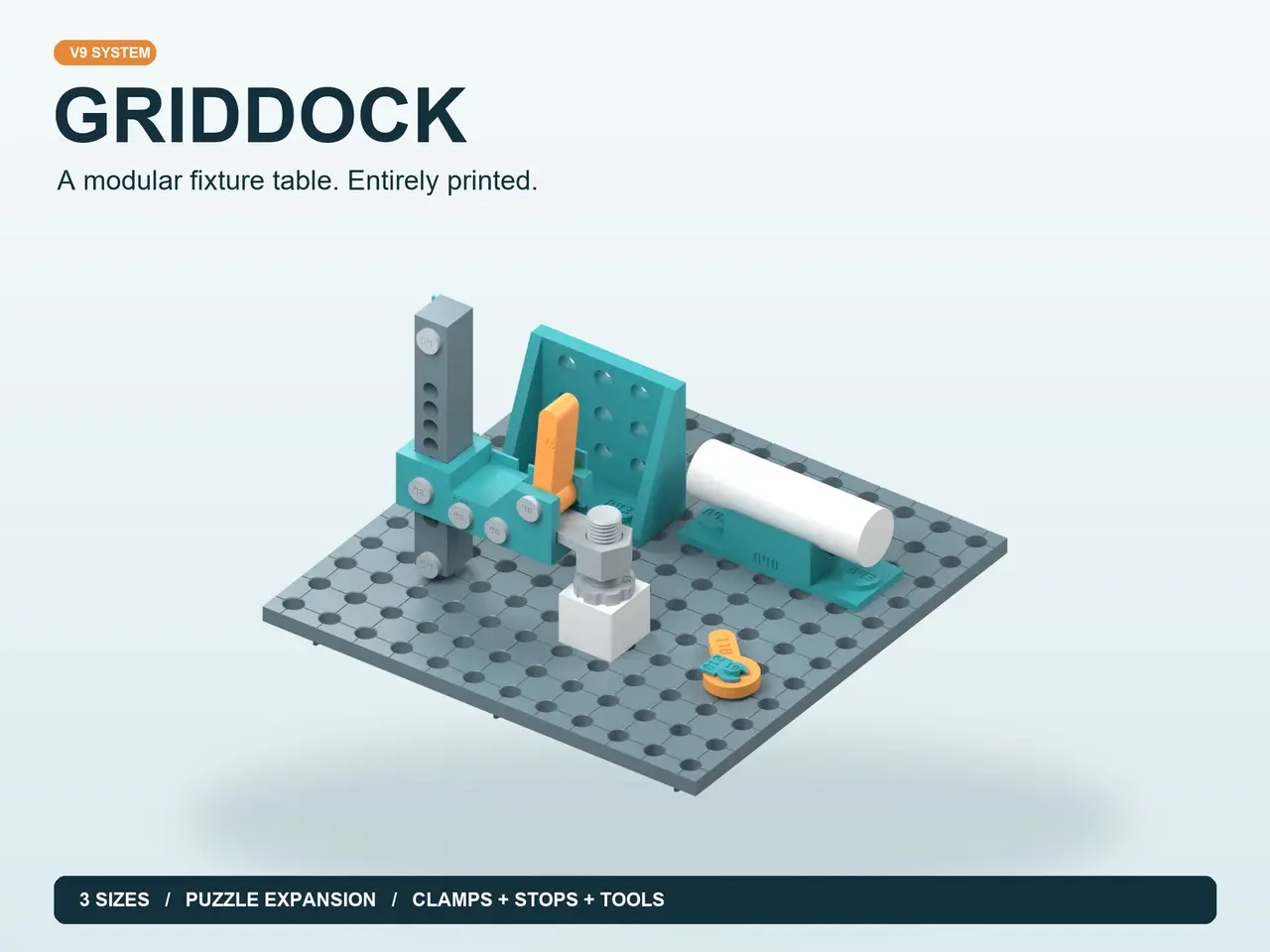
GridDock — Modular Fixture Table, Clamps & Assembly Tools
por Torii Creative Studio en Printables
Printed fixture table: 3 sizes, puzzle tiles, clamps, fences, supports and assembly tools. Parametric CAD included.
Licencia
Solo uso personalCC BY-NC 4.0 — Atribución, no comercial
Puedes imprimirlo y modificarlo para uso personal dando crédito. No se permite vender las impresiones.
Al descargar aceptas respetar la licencia y dar crédito a Torii Creative Studio.
Archivos (72)
- A10.stl STL · 91 KB
- A11.stl STL · 38 KB
- A12.stl STL · 31 KB
- A13.stl STL · 133 KB
- A14.stl STL · 75 KB
- A15.stl STL · 71 KB
- A16.stl STL · 76 KB
- A17.stl STL · 72 KB
- A18.stl STL · 80 KB
- A19.stl STL · 24 KB
- A20.stl STL · 72 KB
- A21.stl STL · 79 KB
- A22.stl STL · 103 KB
- A23.stl STL · 35 KB
- A24.stl STL · 68 KB
- A25.stl STL · 65 KB
- A26.stl STL · 70 KB
- A27.stl STL · 154 KB
- A28.stl STL · 76 KB
- A29.stl STL · 81 KB
- A30.stl STL · 80 KB
- A31.stl STL · 13 KB
- A32.stl STL · 30 KB
- A33.stl STL · 96 KB
- A34.stl STL · 27 KB
- A35.stl STL · 133 KB
- A36.stl STL · 114 KB
- A37.stl STL · 83 KB
- A38.stl STL · 121 KB
- A39.stl STL · 80 KB
- A40.stl STL · 25 KB
- A41.stl STL · 16 KB
- A42.stl STL · 46 KB
- A43.stl STL · 83 KB
- A48.stl STL · 67 KB
- A49L.stl STL · 131 KB
- A49R.stl STL · 107 KB
- A50L.stl STL · 43 KB
- A50R.stl STL · 67 KB
- A51.stl STL · 43 KB
- A52_LOOSE.stl STL · 460 KB
- A52_TIGHT.stl STL · 391 KB
- A53.stl STL · 867 KB
- A54.stl STL · 68 KB
- A55.stl STL · 31 KB
- A56.stl STL · 19 KB
- A57.stl STL · 7 KB
- A58.stl STL · 104 KB
- B01_LOOSE.stl STL · 555 KB
- B01_TIGHT.stl STL · 555 KB
- B02_LOOSE.stl STL · 1,1 MB
- B02_TIGHT.stl STL · 1,1 MB
- B03_LOOSE.stl STL · 1,9 MB
- B03_TIGHT.stl STL · 1,9 MB
- B04_LOOSE.stl STL · 561 KB
- B04_TIGHT.stl STL · 561 KB
- B05.stl STL · 4 KB
- GridDock_Parametric_Plate_LOOSE.f3d F3D · 512 KB
- GridDock_Parametric_Plate_TIGHT.f3d F3D · 489 KB
- GridDock_System_V9.f3d F3D · 17,7 MB
- Categoría
- Herramientas
- Formatos
- STL, F3D, STEP, PY, PDF
- Descargas
- 34
- Publicado
Sobre este modelo
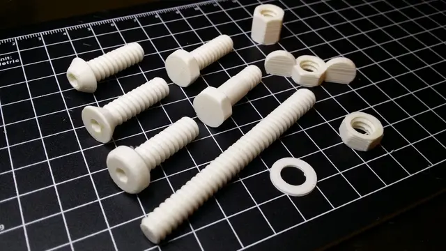
Build your own small fixture station GridDock is a modular, fully printed table for holding, locating and supporting small parts during cold assembly. Start with one plate and a few stops, then add the fixtures you actually need. The hardware is printed too: quarter-turn caps, dogs, cross-keys, axles and retaining clips. Included: 120 / 180 / 240 mm tables, expandable puzzle tiles, TIGHT and LOOSE fits, a parametric plate source, clamps, fences, squares, supports, small-parts accessories and dedicated assembly tools. Native Fusion F3D, STEP, print-oriented STL and complete illustrated manuals in English and Polish are supplied. New: easier caps and centred cross-key assembly A58 tool-ready cap + A55 short socket key: A58 is a drop-in alternative to the original A13 bayonet cap. Six external flats give the short key a positive grip. Hold the pin and turn only 90 degrees from below. A55 requires A58; it does not fit round A13. The original A13 remains available.
A56 cradle + A57 pusher: align the pin slot with the feed channel, place A31 flat in the channel, and press until the finger pad meets the end stop. The fixture supports the pin end and centres the cross-key. Use gentle hand pressure, then inspect both projecting ears. No hammering or glue is required for the first dry-fit check.
Choose your table Plate Size Hole grid
B01 120 x 120 mm 6 x 6
B02 180 x 180 mm 9 x 9
B03 240 x 240 mm 12 x 12
B04 120 mm puzzle tile Repeat to expand
The compatible grid pitch is 20 mm. Shallow reference lines cross through the hole centres. Part identifiers are discreetly placed underneath the plates. Print the working face down using the supplied STL orientation.
Puzzle expansion: connect B04 tiles with B05 bow-tie keys; add A29 seam straps where reinforcement is needed. Support the joined table on a flat surface. The manual shows a 360 x 240 mm example; editable plate sources are included.
Post lever clamp A vertical post mounts in one table hole. The arm slides between eight indexed positions and locks with a removable printed pin; the M16 x 2 spindle provides fine height adjustment. The upright lever gives about 2.1 mm quick release. Nominal work height: 1-81 mm. One clamp uses 21 printed pieces and no purchased fasteners. Remove the height pin only with the clamp unloaded and the arm supported.
The clamp uses A49L/R post halves, A50L/R arm halves, A51 lever, one A52 follower (TIGHT or LOOSE), A53 spindle, A48/A54 axles and shared A12/A31/A13 hardware. Print T96_TIGHT, T96_LOOSE and T97 first to choose the thread fit. See the post-clamp chapter in the assembly manual for quantities and assembly order. Rotary fence and work supports A35 provides a 0-90 degree angle setup. Release both mounting caps before rotating the fence, then hold the dogs and relock them. Its engraved scale is a setup aid. A36/A38 risers support work 20/40 mm above the table; A42 offers 5/10/15/20 mm steps. A40 prisms support round stock in pairs.
Complete accessory catalogue The following cards show every accessory part in this release. Print matching quantities from the assembly manual rather than one of everything. Alternative thread fits are choices, not extra parts to install together. Accessory card 1
- A14 — Low straight stop.
- A15 — Tall straight stop.
- A16 — Inside corner stop.
- A17 — V cradle.
- A18 — Flat work support.
- A19 — Sliding fence.
Accessory card 2
- A21 — PCB edge cradle.
- A22 — Cable comb.
- A23 — Parts tray.
- A24 — Long square fence.
- A25 — Round stop.
- A26 — Thin work stop.
Accessory card 3
- A27 — Point support.
- A28 — 45 degree support.
- A29 — Seam reinforcement strap.
- A30 — Round component cup.
Descripción original del autor, publicada en Printables.