FMS Ranger 1220 taildragger conversion
por Nicholas Koch en Thingiverse
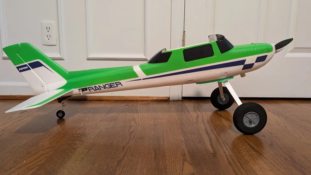
After using the original version of the 3D-printed landing gear mount (https://www.thingiverse.com/thing:7240015 by ANGL3GR1ND3RZ) and the original wheels of my FMS Ranger 1220mm, I found that I still couldn't taxi on grass without nosing over. The center of gravity was nearly directly above the...
Licencia
Uso comercial permitidoCC BY-SA 4.0 — Atribución, compartir igual
Puedes usarlo y modificarlo dando crédito; las versiones modificadas deben compartirse con la misma licencia.
Al descargar aceptas respetar la licencia y dar crédito a Nicholas Koch.
Archivos (1)
- Categoría
- Para tu impresora
- Formatos
- STL
- Descargas
- 2
- Publicado
Sobre este modelo
After using the original version of the 3D-printed landing gear mount (https://www.thingiverse.com/thing:7240015 by ANGL3GR1ND3RZ) and the original wheels of my FMS Ranger 1220mm, I found that I still couldn't taxi on grass without nosing over. The center of gravity was nearly directly above the landing gear, and with the CG higher off the ground, any resistance to forward motion at the wheels from uneven terrain provided enough leverage to nose-over the plane. I still had to hand launch, and my landing still ended in a nose-over. This remix of the original FMS Ranger 1220 "Texas Taildragger" aims to improve upon the location of the landing gear relative to the CG by bringing the landing gear forward about 3-cm by angling the gear forward. Typically, there should be about a 20-degree angle between the CG and landing gear, which this remix aims to provide. Perhaps not so coincidentally, this aligns the axles of the landing gear with the pontoon mounting point. The angle of the landing gear support to the ground during landing is improved. I also switched to 4" wheels. In this configuration, there's about 5 3/8" of prop clearance. See the attached photos. Additionally, the steering of the rear wheel is accomplished by indirectly coupling the control horn to the rudder via plates mounted on either side of the rudder to make a "control horn sandwich". The converted Ranger will now taxi, fly and land like a dream. No more nose-overs! To attach the 4" wheels with the axles I ordered, it was necessary to enlarge the holes so the axles could be mounted. If there is one thing I'd improve, it would be to order 5/32" axles that require smaller mounting holes. After drilling out the holes, only about 1.5 to 2mm of aluminum remained around the rim of the mounting hole, and drilling out aluminum is tricky business. Hint: use oil, some sacrificial backer material, and stop when the drill grabs the material to avoid tearing the aluminum. This happens just as the drill is about to pass through. At this point, put the drill in reverse and push through the last bit of material. If you can find an axle that's compatible with the larger wheel size and existing axle mounting hole, you can avoid drilling the aluminum. Additional hardware: 4" DU-BRO Super Lite XL Wheels | Ultra-Lightweight RC Aircraft Wheels ($16) DU-BRO Nickel Plated Shaft & Wheel Collars (5/32") ($3.50) DU-BRO Spring Steel Axle Shafts – Heavy-Duty RC Landing Gear Axles - 5/32" ($10) Hobby Park 60x25mm tail wheel' from Amazon (same as the original poster, ANGL3GR1ND3RZ) (4) M3-0.5 hex nuts (2) M3 -0.5 16mm screws (5) M3 -0.5 10mm screws (3) original M3 10mm hex screws from the plane -Use three of the original 10mm screws from the plane to mount the landing gear to the printed bracket with the three hex nuts -Use four of the 10mm screws to connect the front of the bracket to the four pontoon mounting holes. -Use the remaining 10mm screw and nut to mount the rudder plates that couple with the control horn of the rear wheel. -Use the 16mm screws to connect the rear of the bracket to the two front holes of the original landing gear location. Out of the package the axles and wheels will not spin freely. Polish the axles with increasing grits of sandpaper. Mount the tip of the axle in a Dremel or drill. Hold the sandpaper to the axle as it spins in the drill, starting with a low grit of 100 or 120, then increasing to 220, 400, and 800 grits. Move the sandpaper over the axle as it spins. Secondly, drill out the axle holes in the wheels with a 5/32" drill bit. Run the bit at a high rate of speed while moving in and out of the axle hole. You shouldn't notice material being removed. You want a tight-fitting wheel that spins freely. Once the wheels and axles are mounted, cut off the excess length with a Dremel or angle grinder. Additionally, make a small flat spot on the axle for the set screw of each axle collar. Happy flying!
Descripción original del autor, publicada en Thingiverse.