CORE One Pins Mod 5G
por DET-Man en Printables
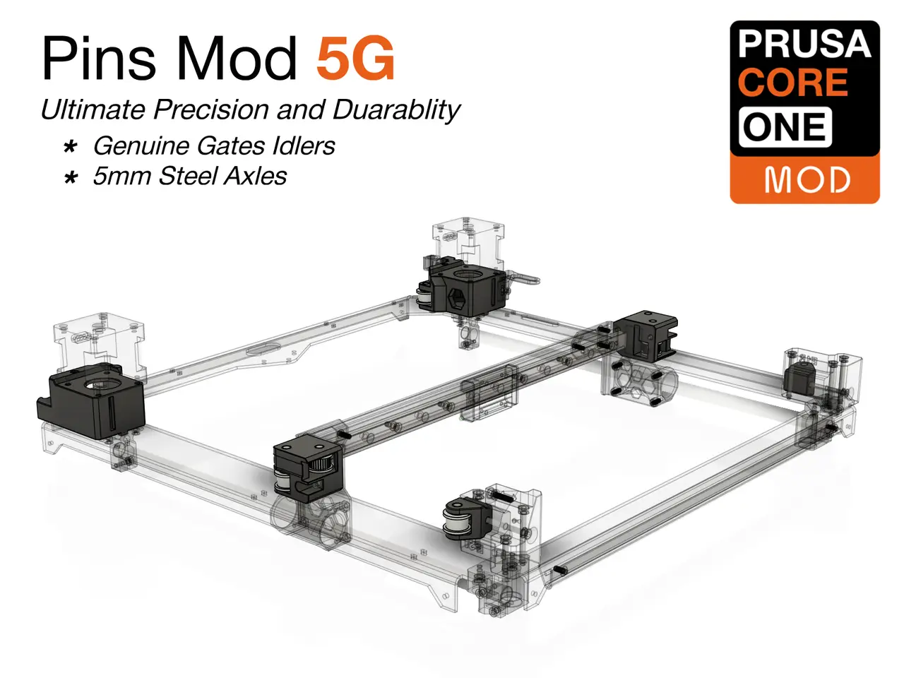
The ultimate 🚀 motion system upgrade for the XY gantry of the CORE One 🥰: 5mm steel axles and genuine Gates idlers 😎.
Licencia
Revisa las condicionesEl autor usa su propia licencia. Revisa sus condiciones en la página original antes de compartir, modificar o vender.
Al descargar aceptas respetar la licencia y dar crédito a DET-Man.
Archivos (9)
- Motor Mount Left - 5G.3mf 3MF · 141 KB
- Motor Mount Right - 5G.3mf 3MF · 157 KB
- XY Carriage - 5G.3mf 3MF · 140 KB
- Belt Tensioner - 5G - Heat Set Insert.3mf 3MF · 87 KB
- Belt Tensioner - 5G - Square Nut.3mf 3MF · 88 KB
- Tools - Spacer 0_4.3mf 3MF · 26 KB
- Tools - Spacer 0_6.3mf 3MF · 31 KB
- Tools - Spacer 0_8.3mf 3MF · 31 KB
- CORE One Pins Mod 5G.f3d F3D · 24,8 MB
- Categoría
- Para tu impresora
- Formatos
- 3MF, F3D
- Descargas
- 127
- Publicado
Sobre este modelo
The 🥰 CORE One is an excellent printer with a well-designed stock system, but the Pins Mod offers mechanical improvements for enthusiasts seeking enhanced precision and reliability. Inspired by the VORON community, it upgrades the XY gantry system by replacing the standard M3 bolts used for idler mounting with 5mm steel axles (pins) and genuine Gates idlers. What's the new with 5G: While the original Pins Mod replaces the M3 bolts with 3mm pins, keeping the stock Prusa idlers and requiring only minimal changes to the printed parts, this Pins Mod 5G leaves this comfort zone: Parts are beefed-up and optimized to use 5mm axles and genuine Gates idlers, of course while keeping full compatibility to other stock parts of your printer. Key Improvements - Eliminated Idler Play on the M3 bolts
- Enhanced Durability by using genuine Gates Idlers for 5mm shafts
- Smoother Operation that reduces vibration and mechanical noise
- Corrected Gen2 Motor Pulley Clearance: Restores the original GT2-style pulley clearance to prevent rubbing on the stock motor mount parts
- Toothed Idler Integration: Optimizes belt engagement using purpose-built toothed idlers; reposition the idler to account for the different pitch-circle diameter and keep the belt path parallel
- Improved Reliability for the Belt Tensioner mechanism by using a heat set insert (optional)
CORE One L Companion Parts
The XY Motor Mounts for the Core One L require slightly different parts. Find these adapted mounts in the companion model: Core One L Pins Mod 5G. All other parts and instructions are exactly the same, just print those two replacement parts.
Question and Answers There is the Pins Mod already - why this 5G variant? 🤔
The 3mm Pins Mod works great - full stop - and it still has it's place: It reuses the stock idlers and requires only a minimal BOM. But me (and others) have experienced quality and durability issues with the stock Prusa idlers, with bearings failing right from the start or within the first year of use. So the route was set for the Pins Mod 5G, using 5 mm pins and high quality, precision, genuine G ates idlers which should last about the lifetime of the printer in this setup.
GT 1.5 and the Gen 2 Upgrade: Do I still need this mod? 🤔
Yes 😎 and with the GT 1.5 / Gen 2 belt change, the Pins Mod (5G) is even more valuable. The GT 1.5 / Gen 2 upgrade improves the belt system, but it does not eliminate the radial play introduced by the stock M3 idler mounting bolts. The Pins Mod addresses that remaining weakness by replacing the bolts with precision steel pins, making the idler assembly more rigid, smoother, and more consistent. In addition, there is a Gen2-specific fix: The new motor pulleys included in the Gen2 upgrade kit have a slightly larger outer diameter and can rub on the stock Motor Mount printed parts. This is corrected by restoring the same pulley clearance that was present with the GT2 pulleys.
Assembly The assembly steps are very similar to original Pins Mod (with 3mm pins) but due to the larger diameter pins much easier and safe. General Assembly Rules - The holes in the printed parts are intentionally undersized. Follow the instructions below to get a perfect fit for the 5mm pins, independently of your slicer settings.
- ⚠ Critical: Never force-push pins through bearings - any stress on the inner bearing race can cause permanent damage; if required, slightly sand down the pin so that the idler can slide onto it without any force.
- Avoid any load on the bearing shells and printed parts during assembly. Use the provided spacers tools to keep the load away from the bearing (but rather on the flange of the idler) and also to prevent the printed part from bending.
- All holes for the 5mm pins are going through the complete part. This allows you to: - Easily prepare the holes from both sides of the part
- Use a 5mm pin punch (or a slightly undersized 5mm pin / shaft / bolt) to align the idler from one side while pressing in the pin from the opposite site
Pin Preparation
Initial Preparation - Ensure pins have a slight chamfer on both ends
- Test-fit each pin through idler bearings completely
Sizing Process (if pins are oversized) - Secure pin in cordless drill chuck
- Use 180-grit sandpaper to uniformly reduce diameter
- Rotate drill while applying light, even pressure with sandpaper
- Work the entire shaft length for consistent sizing
- Reverse the pin the the drill and repeat the steps on the now accessible areas
- Clean pin thoroughly and retest bearing fit
- Repeat process until pin slides freely through bearings - Typical sizing time: 30 seconds per pin
Quality Check: Final pins should insert smoothly into bearings with no resistance or binding
Printed Parts - Hole Sizing Tip: The process is really easy, but print yourself some spare parts and test what works best for you!
The 5mm pins are designed to be press-fitted into the printed parts. To ensure a secure fit without cracking the rigid PC-CF part, aim for a measured hole diameter of 4.95mm. On a well-tuned printer, this fit should be nearly perfect right off the build plate, though holes are intentionally slightly undersized. To efficiently and reliably get the perfect fit, here is what you can do: - Required tools: - 5.0mm drill bit
Descripción original del autor, publicada en Printables.