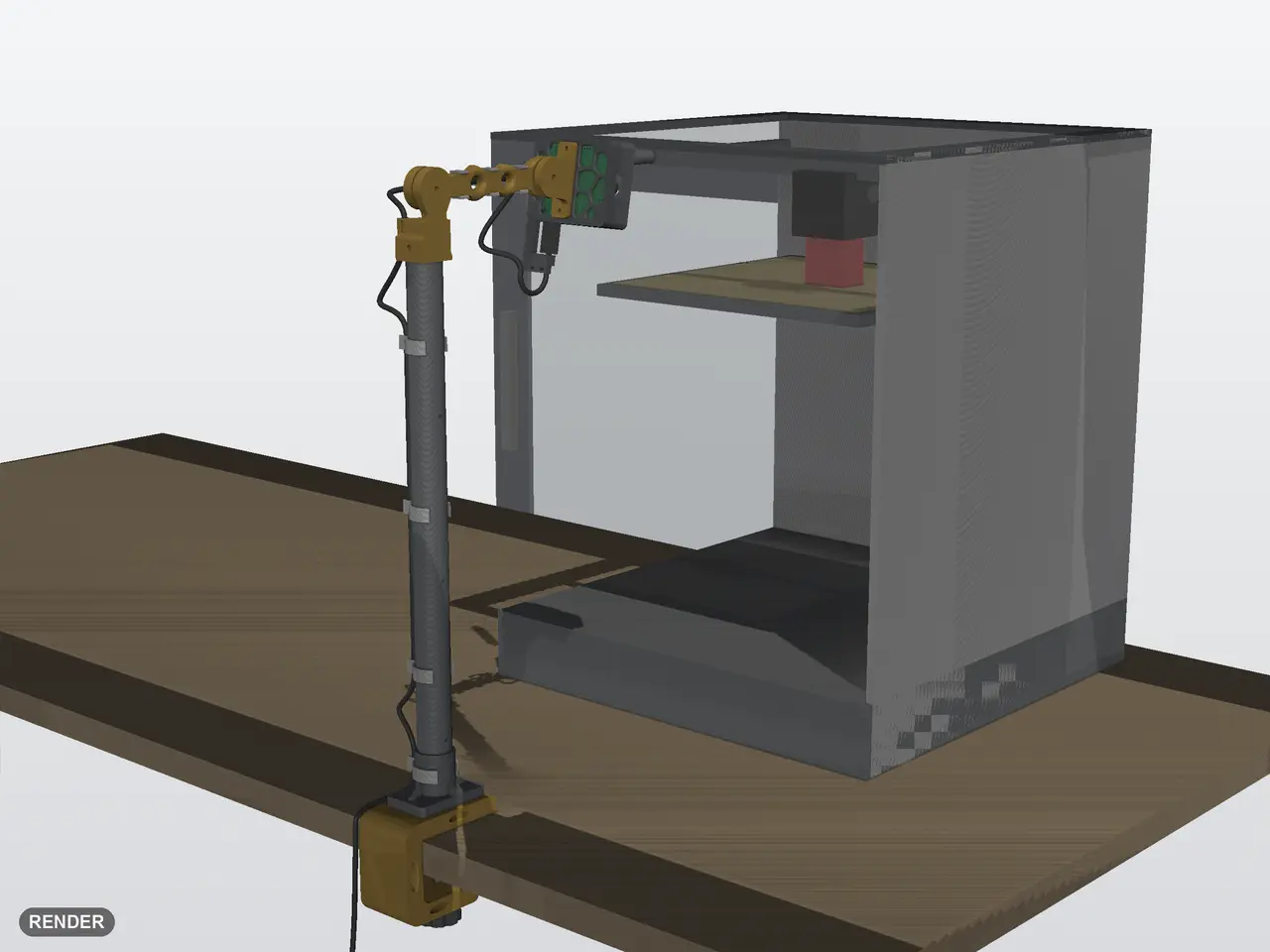
CoralBoard SL Printer Camera Stand: Watches Your Print Bed from Beside Any Printer
por Borja en Printables
Case and camera pod for the CoralBoard SL on a tilt/pan arm, with a desk clamp or sand base, aimed at your print bed.
Licencia
Solo uso personalCC BY-NC 4.0 — Atribución, no comercial
Puedes imprimirlo y modificarlo para uso personal dando crédito. No se permite vender las impresiones.
Al descargar aceptas respetar la licencia y dar crédito a Borja.
Archivos (34)
- test_coupon_tilt_joint_x1.step STEP · 1,3 MB
- foot_b_sand_base_tray_x1.stl STL · 1,5 MB
- test_coupon_tilt_joint_x1.stl STL · 403 KB
- foot_b_sand_base_lid_x1.step STEP · 12,3 MB
- foot_b_sand_base_tray_x1.step STEP · 18,1 MB
- arm_x1.stl STL · 10,4 MB
- camera_cradle_x1.step STEP · 134 KB
- camera_cradle_x1.stl STL · 197 KB
- cable_clip_pole_x3.stl STL · 21 KB
- pole_segment_x3.step STEP · 179 KB
- pole_segment_x3.stl STL · 128 KB
- cable_clip_arm_x3.step STEP · 116 KB
- cable_clip_arm_x3.stl STL · 6 KB
- pod_case_front_x1.stl STL · 2,9 MB
- tilt_bracket_x1.step STEP · 681 KB
- tilt_bracket_x1.stl STL · 1,4 MB
- cable_clip_pole_x3.step STEP · 90 KB
- pod_case_back_x1.stl STL · 2,9 MB
- foot_a_clamp_knob_x1.stl STL · 48 KB
- foot_a_cable_clip_hub_x1.stl STL · 22 KB
- arm_x1.step STEP · 1,9 MB
- foot_a_cable_clip_hub_x1.step STEP · 90 KB
- foot_a_clamp_hub_x1.stl STL · 90 KB
- foot_a_clamp_hub_x1.step STEP · 204 KB
- foot_a_clamp_pad_x1.step STEP · 11 KB
- foot_a_clamp_knob_x1.step STEP · 99 KB
- foot_a_clamp_pad_x1.stl STL · 24 KB
- pod_case_back_x1.step STEP · 6,7 MB
- foot_a_clamp_body_x1.step STEP · 904 KB
- elbow_x1.step STEP · 1,5 MB
- pod_case_front_x1.step STEP · 6,8 MB
- elbow_x1.stl STL · 4,5 MB
- foot_b_sand_base_lid_x1.stl STL · 4,8 MB
- foot_a_clamp_body_x1.stl STL · 8,7 MB
- Categoría
- Para tu impresora
- Formatos
- STEP, STL
- Descargas
- 0
- Publicado
Sobre este modelo
What it is: a case for the CoralBoard SL (Synaptics Astra SL2610 dev board) with its OV5647 camera in one pod, on a tilt and pan arm, on a pole that stands beside any printer and looks in through the door. The board can then run on-device artificial intelligence (AI) print-failure detection (spaghetti, detached parts) on what the camera sees. This listing is the printed hardware; the detection software is your choice and is not included. Status, please read: computer-aided design (CAD) for the Printables CoralBoard Cases and Mounts contest, version 6. Not printed yet: every picture is a CAD render labelled RENDER. Fits were designed from the official reference CAD (no board in hand), with clearances from my printer's measured tolerances. Physical fit and load validation have not been performed; computed stress is not printed-strength evidence. Print the small test coupon first (see below). What is new in version 6: the arm, elbow, tilt bracket and clamp body are rounded organic shapes (lofted sections, rounded openings in the arm and clamp), and the case halves and sand base carry Voronoi cells: open vent cells in the case, a relief pattern on the base lid and tray wall. The joint teeth, bores, bolt holes, board standoffs and mating faces are unchanged, so the parts take the same screws and hardware. All printed parts together (one of each file, solid plastic) weigh 925 g against 979 g for the earlier plain design. Why this one - No printer adapter: it stands on the desk next to the printer, so it suits enclosed and open printers alike and nothing touches the printer.
- Board location and cooling: the electronics sit outside the printer chamber and use passive vents; board temperatures have not been measured.
- Power cable routed, not dangling: the USB-C cable clips into a strain-relief hanger under the pod, 3 snap clips on the arm, one on the elbow and one per pole segment, with slack loops past the tilt, elbow and pan joints (checked in CAD with the organic arm, elbow, bracket and clamp across 29 poses from tilt -80 to +10 deg and pan +-90 deg: minimum clearance to every part 0.71 mm. That sweep used the earlier case halves; the Voronoi case changes only the flat front and back plates, and the sweep was not re-run with it).
- Ports reachable with the pod closed: USB-C power (opening fits a straight or right-angle plug up to 12 x 7 mm), USB-A, microSD (fingernail slot), Qwiic, battery and I2S connectors, buttons and LEDs. Voronoi vent cells in the front and back halves.
- Camera and board in one pod: the stock 15 cm camera ribbon stays inside the case (route about 68 mm).
- Holds its pose: both arm joints are toothed rosettes clamped by an M4 wing nut (15 deg and 10 deg steps, so any pitch in 5 deg steps); pan is a 360 deg thumb-screw clamp.
- Two feet, pick one: A, desk-edge clamp for desks 10 to 40 mm thick, or B, 220 mm sand base for any flat surface.
- No supports by design: every part is pre-oriented flat or on its side, cable clips included (checked with a geometric 45 deg overhang scan, not yet in a slicer).
- Strength: a computer stress check (finite element analysis: 150 g pod at the worst tilt plus a 16 N side push, the clamp also with a 300 N bolt preload, solid PLA assumed, 40 MPa allowable) gives these safety factors at the finest mesh (lowest across four mesh sizes): arm 1.70 (1.69), elbow 2.10 (2.10), tilt bracket 2.04 (1.95), clamp body 3.06 (3.00), against a 1.5 target. The Voronoi case halves and sand base carry no real load and had no stress check; they passed watertight, minimum-wall (3 mm struts), overhang and zero-interference fit checks (case halves against the board, camera, cradle, bracket and each other; lid against tray). These are calculations for solid plastic, not tests of a printed part with 2 walls and 15 % infill.
What the camera sees The OV5647 sees 54 x 41 deg. Coverage was computed against a generic enclosed printer (256 x 256 mm bed, glass door and lid; the door and lid frames block the view), lens straight in front of the bed centre: - 300 mm from the bed centre (lens about 10 cm in front of the door): 96 % of the bed in view, bed fills 24.7 % of the image. Recommended: 3 pole segments, arm level, tilt -10 deg.
- 400 mm: 100 % of the bed in view, fills 12.2 % of the image.
- 600 mm: 100 % of the bed in view, fills 4.2 % of the image.
- 1000 mm: 100 % of the bed in view, fills 1.1 % of the image.
Closer is better. Raising the lens above the door's top frame bar does not help (the frame cuts off the back of the bed), so the stand puts the lens just under that line, tilted slightly down. Refocus the lens: the OV5647 mini module is sold as fixed focus, 1 m to infinity, so at 300 to 600 mm the picture is soft. If your module's lens barrel turns, turn it until the bed is sharp at your distance. I have not checked this on a real module. Stability (computed, not measured) Computed for the earlier plain parts with the same joints and footprint; the version 6 parts are slightly lighter and these numbers were not recomputed for them. - Foot A, clamp: about 16 N push at the pod before it rocks, assuming 300 N hand-tight clamp force (a guess).
- Foot B, sand base: tips at about 5.7 N at the pod with 2.3 kg of dry sand; about 14 N with steel shot instead (6.5 kg, density assumed).
Parts list (hardware) - Power: a 5 V 3 A USB-C supply (the board takes 5 V only and does not negotiate USB-PD, so use a plain 5 V 3 A USB charger with a separate cable; a Raspberry Pi 15 W USB-C PSU also works if its captive 1.5 m cable reaches your socket) and a round USB-C cable 3-4 mm thick, at least 1.8 m (847 mm from the pod to the desk edge on the clamp foot, plus 1 m to reach a socket; buy 2.0 m). Straight plug up to 25 mm long, or right-angle. 1-2 small cable ties (2.5 mm).
- Board and camera: CoralBoard SL, Arducam OV5647 mini camera module (25 x 24 mm, the module Google names for this board)
- Camera ribbon: 15-pin 1.0 mm (camera) to 22-pin 0.5 mm (board) FFC, 15 cm, Pi Zero style, for example the Pimoroni Pi Zero camera cable. Check the pinout against the board's camera connector before buying: Synaptics note that non-matching pinouts need an adapter.
- Pod: 4x M3x20 pan head (case and board, self-tapping into the back half), 2x M3x12 + 2x M3 nut (camera cradle), 2x M3x10 + 2x M3 nut (tilt bracket), 4x M2x6 self-tapping (camera)
- Arm: 2x M4x25 + 2x M4 wing nut + 4x M4 washer (elbow and tilt joints), 1x M4x12 + 1x M4 nut (pan clamp)
- Pole: optional 1x M3x30 + 1x M3 nut per joint (cross-lock)
- Foot A, clamp: 1x M6x60 hex bolt + 1x M6 nut, 2x M4x20 + 2x M4 nut, 2 felt or rubber pads
- Foot B, sand base: 4x M3x8 self-tapping, 8 stick-on rubber feet 10 mm, about 2.3 kg dry sand in a bag (or steel shot)
Print settings - PLA, 0.2 mm layers, 0.4 mm nozzle, stock profile (2 walls, 15 % infill)
- No supports; files are pre-oriented
- Pod, arm and 3 pole segments: about 151 g, about 5.6 h
- Foot A, clamp: about 74 g, about 2.6 h (clamp body prints on its side)
- Foot B, sand base: about 276 g, about 8.9 h (tray open side up; needs a 220 mm bed)
- Grams and hours are estimates from the mesh, not from a slicer.
Print first: test coupon test_coupon_tilt_joint_x1 is the camera cradle, the tilt bracket and a short arm stub, in the plain earlier shape: the toothed joint, cradle pocket and bolt holes are the same as on the organic parts. Bolt the joint up hand tight and check that it holds its angle and that your camera fits the cradle before printing the rest. Assembly - Camera: press the camera into the cradle pocket and fix it with 4 M2x6 screws. Plug the 15-pin end of the ribbon into the camera and pass the ribbon through the slot behind the cradle.
Descripción original del autor, publicada en Printables.