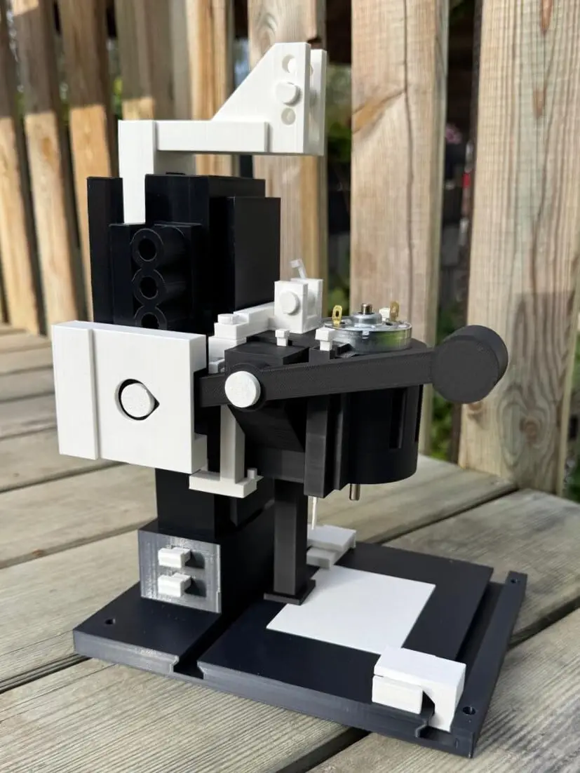
Compact PCB Drill Press – R3.1
por Christoph Fehleisen en Thingiverse
I wanted a small drill press for making my own circuit boards, so I designed one with a fully 3D-printable frame that assembles without any metal screws, nuts or bolts. Even the connecting pins and wedges come straight from your printer! It’s easy to put together, easy to take apart and intuitive...
Licencia
Solo uso personalCC BY-NC-SA 4.0 — Atribución, no comercial, compartir igual
Uso personal dando crédito; sin fines comerciales y las modificaciones con la misma licencia.
Al descargar aceptas respetar la licencia y dar crédito a Christoph Fehleisen.
Archivos (10)
- 01_RAHMEN_R3_FUENF_HOEHEN.3mf 3MF · 110 KB
- 02_SCHLITTEN_HEBEL.3mf 3MF · 43 KB
- 03_KLEINTEILE.3mf 3MF · 37 KB
- 05_R3_1_RUECKHOLUNG_VERSTAERKT.3mf 3MF · 73 KB
- 06_R3_BOLZEN_KEILE.3mf 3MF · 67 KB
- 04_OPTIONAL_DISTANZRINGE.3mf 3MF · 33 KB
- 11_NUR_ERSATZKEILE_A_2x.3mf 3MF · 2 KB
- 07_R3_OPTIONAL_PARKUNTERLAGEN.3mf 3MF · 2 KB
- 00A_R3_STECKBOLZEN_PASSUNG.3mf 3MF · 18 KB
- 00B_R3_SCHIEBETRAEGER_PASSUNG.3mf 3MF · 28 KB
- Categoría
- Herramientas
- Formatos
- 3MF
- Descargas
- 100
- Publicado
Sobre este modelo
I wanted a small drill press for making my own circuit boards, so I designed one with a fully 3D-printable frame that assembles without any metal screws, nuts or bolts. Even the connecting pins and wedges come straight from your printer! It’s easy to put together, easy to take apart and intuitive to use. Just add the motor, tool holder, drill bit, return spring and electronics to complete the build. You lower the drill with the hand lever and guide it back up while a spring lifts the head. There are five height positions, an adjustable slide guide and a replaceable insert underneath the PCB. What do the numbers mean? The numbers at the beginning of the 3MF filenames identify the print plates. Each plate contains a group of parts that belong together. Whats on the files: 00B Fit test for the two rear rails and their sliding carrier 01 Base and column 02 Carriage, motor cap, hand lever and parking support 03 Small assembly parts, drilling insert and PCB clamps 04 Optional motor spacer rings 05 Reinforced spring-return mechanism 06 Pins, retaining wedges and spacer rings for the return mechanism 07 Optional parking-support extensions for the higher positions 11 Only the two replacement “A” base wedges, 4.8 mm thick The two wedges on plate 11 are already included on plate 03. You only need to print them once. Please start with the test prints Small differences between printers can make a sliding part too tight or a retaining wedge too loose. The test plates let you check this before spending time and filament on the bigger parts. Plate 00 checks the main slide guide and the original pin fit. The slide should move smoothly, with the adjustment wedge taking out most of the play. Plate 00B checks both rear rails together. The carrier should slide onto them without bending or forcing anything. Insert the long pin and its retaining wedge to check the height lock. These are fit tests, not strength tests. If something needs a hammer, stop and check the fit first. Print settings Use PLA and a 0.4 mm nozzle as a starting point. Keep the supplied orientation and print at 100% scale. On plate 01, print the base with 0.24 mm layers, 6 walls and 30% Gyroid infill. For the column, use 0.20 mm layers, 6 walls and 40% Gyroid. Set these individually in your slicer. The column needs supports from the build plate. On plate 02, use 0.20 mm layers, 6 walls and 35% Gyroid for the carriage, motor cap and parking support. Give the hand lever 100% infill. For plate 03, use 0.20 mm layers, 5 walls and 100% infill. For plates 04, 05 and 06, use 0.20 mm layers, 6 walls and 100% infill. For the optional parking extensions on plate 07, use 0.20 mm layers, 5 walls and 30% Gyroid. For the replacement wedges on plate 11, use 0.16 mm layers, 5 walls and 100% infill. These wedges are also included on plate 03, so you only need to print them once. Use a straight-line infill pattern for the 100% parts. Keep the supplied orientation and 100% scale. Apart from the column, start with supports off and check the bridges and holes in your slicer preview. Set the base and column separately in your slicer, even though they share a plate. Do the same for the lever on plate 02. The column needs supports from the build plate. For the other parts, start with supports off and check the preview, especially around bridges and holes. A few things before you start The motor mount is designed around a body approximately 42.1 mm in diameter and 67 mm long. Please measure your motor first. For the return spring, the current calculated starting point is approximately 0.25 N/mm, with 11 N pull at the top and 16 N at the bottom. The mounting-pin spacing changes from about 75 to 95 mm. These are installed dimensions. The spring is still on backorder so thats why its missing in the pictures Start assembly in the lowest height position. Check the movement without power, secure the machine to your workbench and clamp the PCB before drilling. The replaceable insert is there so the drill can pass through the board without damaging the base. Its already fully functional but still a prototype that I’m improving as I build it. #MakersToolsChallenge
Descripción original del autor, publicada en Thingiverse.