Ball-Joint Vise with Weighted Base - 100% printable [UPDATE 14.11]
por hvrkh en Printables
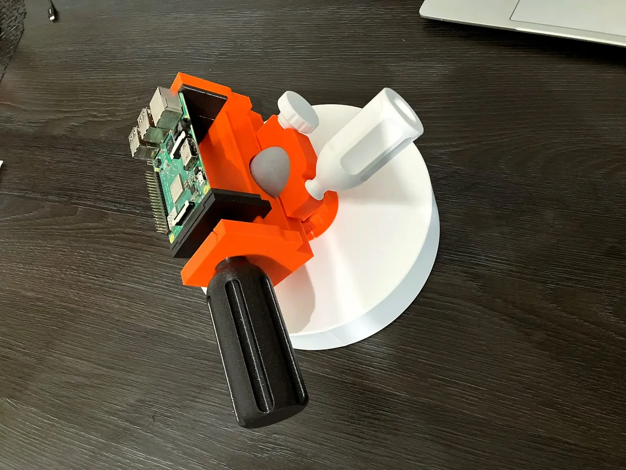
A 3D-printable vise with a ball joint, weighted base with non-slip surface, adjustable positioning.
Licencia
Solo uso personalCC BY-NC-ND 4.0 — Atribución, no comercial, sin derivadas
Solo para uso personal, sin modificarlo y dando crédito. No se permite vender ni redistribuir cambios.
Al descargar aceptas respetar la licencia y dar crédito a hvrkh.
Archivos (22)
- weight plate.stl STL · 11,6 MB
- plug.stl STL · 1,4 MB
- retaining nut.stl STL · 12,3 MB
- ball-joint shaft.stl STL · 22,6 MB
- weight plate - print setting.3mf 3MF · 2,7 MB
- ball-joint shaft - print setting.3mf 3MF · 5,0 MB
- TPU anti-slip3.stl STL · 100 KB
- TPU anti-slip2.stl STL · 100 KB
- TPU anti-slip1.stl STL · 89 KB
- weight plate practical.stl STL · 51,7 MB
- ball-joint shaft_longer (two plates).stl STL · 26,0 MB
- Fixed jaw pad.stl STL · 12 KB
- fixed jaw.stl STL · 8,4 MB
- lead screw pad 1.stl STL · 11 KB
- ball-joint clamping plate.stl STL · 2,6 MB
- lead screw jaw.stl STL · 11,2 MB
- lead screw jaw_full lenght.stl STL · 52,2 MB
- locking bolt.stl STL · 18,1 MB
- clamping lever screw.stl STL · 28,3 MB
- Printing settings.3mf 3MF · 18,8 MB
- locking bolt_v2.stl STL · 19,4 MB
- clamping lever screw_v2.stl STL · 28,2 MB
- Categoría
- Herramientas
- Formatos
- STL, 3MF
- Descargas
- 45
- Publicado
Sobre este modelo
Introduction I’d like to introduce what is probably my most detailed model so far. It’s a vise mounted on a ball joint, allowing you to turn the workpiece and set it at different angles as needed. When the vise is loosened, the moving part retracts into the handle along with its screw. It’s a neat feature that keeps anything from sticking out or getting in the way. The vise is not permanently attached to a workbench. A weighted base with non-slip pads keeps it from moving and holds it in place. The base is essentially a disk that you fill with sand or another material. Non-slip pads are attached to the underside. The ball-joint shaft passes through the center of the weight and is secured from above with a nut. The entire model is 3D-printable, and I’ve included all the required files and instructions below. Apart from the printed parts, you’ll only need some glue and material to fill the weight. Update 14.11. - Practical weight plate: The weight plates don’t have to be just dead weight! I’ve added a plate with handy compartments for screwdriver bits and small parts such as screws, nuts, and connectors. - weight plate practical.stl
- Longer shaft: I’ve added a longer shaft so you can choose the working height that suits you. It also lets you stack more weight plates to add weight and create a more stable base. - ball-joint shaft_longer (two plates).stl
- Updated screws: I’ve updated the clamping lever screw and locking bolt (both ...v2.stl). These have a looser fit than the original versions, so they should work better if you had trouble fitting the original ones.
Instructions and print settings General settings: Print all parts at a 0.15 mm layer height using a slower print profile—for example, Structural or Balanced in PrusaSlicer. 1. Base First, print all the required parts. I’ve also included 3MF files with print settings for most of the parts. - Print the disk (weight plate.stl), which serves as the weight, with 5% Gyroid infill. This leaves large enough cavities inside the disk for it to be filled. To help the disk keep its shape once filled, don’t skimp on material: use 4 perimeters and at least 7 solid top and bottom layers. I printed mine in inexpensive PLA. Print the plug (plug.stl) along with the disk.
- Next, print the ball-joint shaft (ball-joint shaft.stl) and the nut (retaining nut.stl). Use PETG, 30% cubic infill, and 3 perimeters.
- Non-slip pads (TPU anti-slip#.stl): There are 3 versions to choose from. Print them in TPU 95A using the standard print profile. If you don’t have TPU, or want better grip, you can buy self-adhesive non-slip pads at a hardware store.
The parts are now printed. - Make an opening in the disk at the plug location so you can access the infill inside. Then use a sieve to pour or funnel in the filling material. I used sand and dried it in the oven beforehand to help prevent mold from forming over time. Other materials, such as plaster or concrete, should also work, but I haven’t tried them, so I decided to play it safe and use sand. The finished weight came to about 1.8 kg.
- Once the disk is filled, insert the printed plug and close the opening to keep sand and dust from spilling out.
- Use double-sided tape to attach the non-slip pads.
- Pass the shaft through the center of the disk and secure it from above with the nut.
2. Vise First, print all the required parts. I’ve also included 3MF files with print settings for most of the parts. - The vise body (fixed jaw.stl) is already oriented correctly and must be printed in this orientation using organic supports. Use a 0.15 mm layer height, PETG, 3 perimeters, and 20% cubic infill.
- The adjustment handle (lead screw jaw_full lenght.stl) consists of two parts that are printed together in one piece. Once printed, they act as a bearing. There is a 0.15 mm gap between the parts, so it’s very important not to align the seam. Use the same settings as above, but set the seam position to Random. For a two-color effect, you can change the filament color after the bearing section has printed, as I did.
- Print the moving screw (lead screw jaw.stl) using the same settings as above. Standard supports are sufficient for this part.
- Print the jaw pads (Fixed jaw pad.stl, lead screw pad 1.stl) using the same settings as above. No supports are needed.
The parts are now printed. - Push the moving screw about 1 mm into the adjustment handle, then insert both parts into the vise body as shown in the photo. You may not need to push the screw into the handle. The orange part of the adjustment handle shown in the photo is a prototype. The files include an improved version that connects more securely to the vise body. For maximum joint strength, you can glue the parts together.
- Once assembled correctly, you should be able to push the moving screw gently toward the handle. Turn the handle to engage the thread, and the screw should start retracting.
- Open the vise slightly and fit the jaw pads.
The vise is now assembled. 3. Attaching the vise to the base - Print the upper ball-joint clamping plate (ball-joint clamping plate.stl). Use a 0.15 mm layer height, PETG, 3 perimeters, and 20% cubic infill.
- Print the screws (clamping lever screw.stl and locking bolt.stl) using the same settings.
- The screws shown in my photos are printed in PLA, but I recommend using the stronger PETG.
The parts are now printed. - First, screw the fasteners into the vise body to check that they thread in properly and don’t bind. If they do bind, screwing them in and out a few times should clear imperfections from the threads, allowing them to turn more smoothly. If that doesn’t help, you’ll need to print screws designed with greater tolerance for your printer. I’ll add those later.
- Once you’ve checked the screws, place the vise’s spherical socket over the ball joint on the base. Then secure it with the upper clamping plate and both screws. Tighten one screw a little further than the other. The screw with the handle acts as the adjustment lever: loosen it with one hand, reposition the vise, and tighten it again. It’s quick and convenient.
Představení Představuji vám můj asi zatím nejpropracovanější model. Jedná se o svěrák, který je připevněný ke kulovému kloubu a je tak možné si uchycený předmět otočit do různých směrů a náklonů podle potřeby. Pohyblivá část svěráku se při povolování zasouvá i se závitem do madla. To je chytrá vychytávka, která zajistí, že nikde nic netrčí a nepřekáží. Svěrák není pevně upevněn ke stolu. Aby se nehýbal a zůstal na místě slouží základna se závažím a protiskluzovými podložkami. Základna je v podstatě kotouč, který se naplní pískem, nebo jinou náplní a zespodu se na něj nalepí protiskluzové nálepky. Kulový kloub se pak prostrčí středem závaží a nahoře se zajistí maticí. Celý model je kompletně 3D tisknutelný a všechny potřebné modely a instrukce přikládám níže. Kromě tištěných dílů budete potřebovat už jen lepidlo a nějakou náplň do závaží. Návod a tiskové instrukce Instrukce na úvod - vše se tiskne na 0,15mm a na pomalejší chod - tj.: structural nebo balanced v případě Průša profilů. 1. Základna Nejprve si vytiskneme všechny potřebné díly (Přikládám i 3mf soubory, kde je kompletní tiskové nastavení většiny dílů) - Kotouč (weight plate.stl), který bude sloužit jako závaží, je třeba tisknout s 5% výplní typu gyroid, to zajistí, že uvnitř budou dostatečně velké otvory, aby se dal kotouč dobře naplnit zátěží. Aby i se zátěží dobře držel tvar nevyplatí se šetřit na materiálu, takže 4 perimetry a alespoň 7 plných horních a spodních vrstev. Já jsem tiskl z levného PLA. S kotoučem vytiskněte i zátku (plug.stl).
- Další na řadě je osa s kulovitým kloubem (ball-joint shaft.stl) a matice (retaining nut.stl). Materiál PETG, 30% kubická výplň a 3 perimetry
- Protiskluzové podložky (TPU anti-slip#.stl): máte na výběr 3 druhy. Tisk z TPU 95A standardní tiskový profil. Pokud nemáte TPU nebo chcete lepší protiskluzový výsledek, můžete koupit nějaké samolepící protiskluzové podložky v hobby marketu.
Máme vytištěno. - V kotouči si uděláme otvor v místě, kde je zátka tak, abychom se dostali dovnitř k infillu. Následně pomocí cedníku nasypeme/nalijeme výplň. Já jsem použil písek, který jsem předtím vysušil v troubě, abych tam neměl po čase plíseň. Určitě se dají použít i jiné výplně jako sádra nebo beton, ale nemám s tím zkušenost, tak jsem byl konzervativní. dostal jsem se na váhu cca 1,8kg.
- Po naplnění vezměte vytištěnou zátku a otvor uzavřete, aby se písek a prach nesypal ven.
- Prostředkem prostrčím osu a shora ji zajistím maticí.
2. Svěrák Nejprve si vytiskneme všechny potřebné díly (Přikládám i 3mf soubory, kde je kompletní tiskové nastavení většiny dílů) - Samotné tělo svěráku (fixed jaw.stl). je napolohované a musí se tisknout v této poloze s použitím organických podpěr. Pořád platí výška vrstvy 0,15mm. Materiál PETG, 3 perimetry, výplň kubická 20%
- Nastavovací madlo (lead screw jaw_full lenght.stl). Jsou to dva díly a tisknou se v kuse - funguje to potom jako ložisko. Je tam mezera 0,15mm a je velmi důležité aby zde nebyl zarovnaný šev. Tady je stejné nastavení jako výše, ale je třeba tam zapnout pozici švu náhodnou. Pro dobrý barevný efekt můžete jako já vyměnit barvu po vytištění ložiskové části.
Descripción original del autor, publicada en Printables.