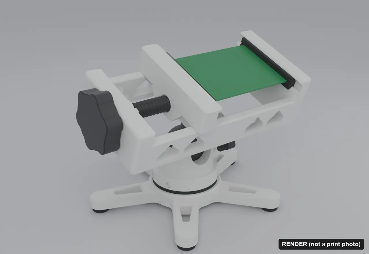
Ball-Joint PCB Holder Vise: Tilts 80 deg, Turns 360, TPU Groove Jaws
por Borja en Printables
Fully printed PCB vise: TPU V-groove jaws, 10-136 mm opening, ball joint tilt with thumbscrew lock, star base.
Licencia
Solo uso personalCC BY-NC 4.0 — Atribución, no comercial
Puedes imprimirlo y modificarlo para uso personal dando crédito. No se permite vender las impresiones.
Al descargar aceptas respetar la licencia y dar crédito a Borja.
Archivos (13)
- pcb_vise_1_foot_tpu_x5.stl STL · 47 KB
- pcb_vise_1_turntable_ring_tpu_x1.stl STL · 75 KB
- pcb_vise_3_clip_x1.stl STL · 78 KB
- pcb_vise_2_lock_pad_tpu_x1.stl STL · 92 KB
- pcb_vise_2_pin_62_x2.stl STL · 53 KB
- pcb_vise_3_jaw_strip_tpu_x2.stl STL · 2 KB
- pcb_vise_3_jaw_carriage_x1.stl STL · 886 KB
- pcb_vise_2_socket_body_x1.stl STL · 1,6 MB
- pcb_vise_3_frame_x1.stl STL · 780 KB
- pcb_vise_2_lock_thumbscrew_accent_x1.stl STL · 1,5 MB
- pcb_vise_2_ball_stud_accent_x1.stl STL · 1,3 MB
- pcb_vise_1_base_star_x1.stl STL · 6,8 MB
- pcb_vise_3_screw_knob_accent_x1.stl STL · 7,3 MB
- Categoría
- Herramientas
- Formatos
- STL
- Descargas
- 23
- Publicado
Sobre este modelo
What it is: a fully printed PCB holder vise on a ball joint. Two TPU strips with a V-groove hold the board by its edges, a lead screw with a 60 mm star knob closes the jaws (opening 10 to 136 mm), the frame tilts up to 80 deg on a 44 mm ball with a thumbscrew lock and turns 360 deg on a five-arm star base with TPU feet. No hardware needed. Status, please read: CAD version 4 for the Printables Vises contest. This vise has not been printed yet: every picture is a Blender render, labelled RENDER, and the numbers below are from CAD. It uses the same 16 mm lead-screw thread profile as the fin-ray desk vise entry, at the 0.20 mm radial clearance its printed coupon picked. How it works - Groove jaws: a fixed jaw bar and a moving jaw carriage on a 206 x 100 mm frame, each with a black TPU 95A strip with a 90 deg V-groove (3.4 mm mouth) that centres a board edge. The strips slide into a hooked pocket from the end and cannot lift out; one strip part fits both jaws (turn it over for the moving jaw).
- Lead screw: 16 mm, 4 mm pitch, through a nut in the carriage, turned by a 60 mm star knob; a clip holds it at the knob end.
- Ball joint: a 44 mm ball on a threaded stud screws into the frame's centre beam. The ball snaps into a three-finger socket; a front notch lets the frame tilt to 80 deg (CAD sweep clear at every base heading). A thumbscrew presses a captive TPU pad onto the ball to lock the angle.
- Turntable base: the socket turns on a spigot over a star base (190 mm feet circle) on a TPU ring for drag; it has no lock. Two 6 mm pins hold it down.
- Stability (CAD estimate): about 555 g with a 170 x 110 mm board; at 80 deg tilt the centre of mass stays at least 32 mm inside the feet. With the long board side along the strips the board clears the base to about 72 deg.
Print settings - PLA (star base, socket, pins, frame, carriage, clip): 0.2 mm layers, 0.4 mm nozzle, 3 walls, 20 % infill, no supports; files are pre-oriented.
- Accent PLA (black in the renders): ball stud, lock thumbscrew, lead screw + knob.
- TPU 95A (jaw strips, lock pad, turntable ring, feet): 0.2 mm layers, slow (about 25 mm/s), 3 walls, no supports. The strips print standing on their roof edge.
- Build volume: the lead screw prints standing on its knob and is 216 mm tall; every part fits a 250 x 210 x 220 mm bed.
- Walls, infill and TPU speed are suggestions, not tuned on a print. Solid volume (upper bound, not a slicer estimate): PLA parts about 743 cm3, TPU parts about 32 cm3.
Parts list (print count) File names start with the assembly step number and end with the count (_x2 = print two). - Step 1: star base x1, foot x5 (TPU), turntable ring x1 (TPU).
- Step 2: socket body x1, pin 62 mm x2, ball stud x1 (accent), lock thumbscrew x1 (accent), lock pad x1 (TPU).
- Step 3: frame x1, jaw carriage x1, lead screw + knob x1 (accent), clip x1, jaw strip x2 (TPU).
Assembly - Press the five TPU feet into the arm tips of the star base and lay the TPU ring on the base.
- Lower the socket onto the spigot and slide the two 62 mm pins through the socket so they ride in the spigot groove.
- Push the TPU lock pad into its pocket from inside the cup, back end first, until it passes the lip. Thread the lock thumbscrew in from the outside and leave it backed off.
- Screw the ball stud into the centre beam of the frame until it seats.
- Slide one TPU strip into the fixed jaw pocket from the end; turn the second strip over and slide it into the carriage.
- Set the carriage on the frame rails, feed the lead screw through the knob end and the carriage nut until its tip sits in the fixed end, then snap the clip into the groove at the knob end.
- Press the ball into the socket past the fingers, set the angle and tighten the thumbscrew.
Descripción original del autor, publicada en Printables.