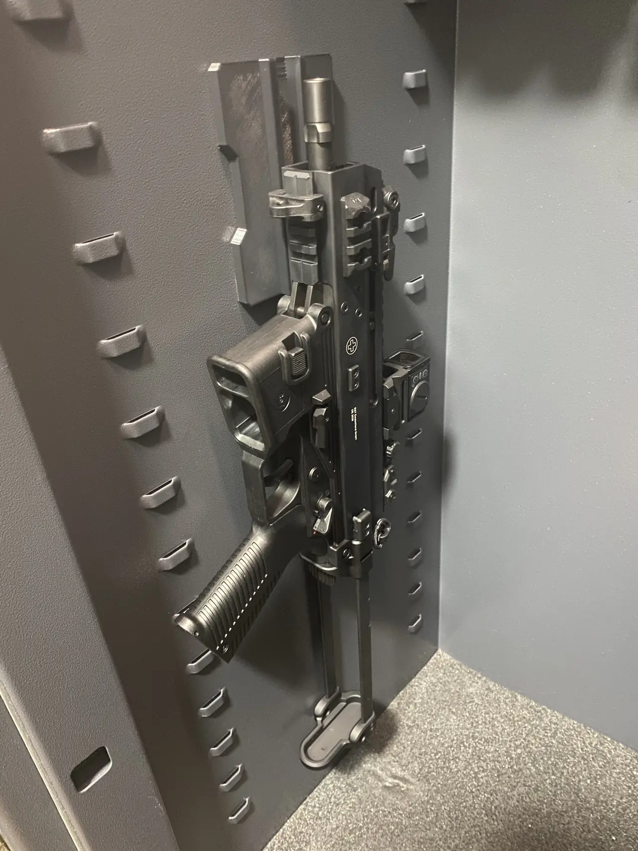
APC9 Magnetic Picatinny Safe Mount
por Aurorachyn en Printables
Magnetic safe-wall storage mount tested with an APC9K Pro. Uses four 20 × 5 mm disc magnets.
Licencia
Solo uso personalCC BY-NC-SA 4.0 — Atribución, no comercial, compartir igual
Uso personal dando crédito; sin fines comerciales y las modificaciones con la misma licencia.
Al descargar aceptas respetar la licencia y dar crédito a Aurorachyn.
- Categoría
- Jardín
- Formatos
- STL
- Descargas
- 4
- Publicado
Sobre este modelo
This mount is designed for stationary storage on a magnetic steel safe wall. Slide the Picatinny rail into the guide from above until it rests on the lower stop. A flared entry helps guide the rail into place. I developed and refined this mount for my APC9K Pro with telescopic stock and folding charging handles, printed it in PLA, and successfully tried it in my own safe. Fit has been checked with this specific configuration. Other rails, accessories and mounting surfaces need their own checks. Firearm Safety Always unload the firearm and verify that the chamber is empty before placing it in or removing it from the mount. Keep the muzzle pointed in a safe direction and your finger off the trigger. This mount is a storage accessory, not a firearm safety device or locking mechanism. Use it only inside a suitable locked safe and follow applicable storage requirements. Check the mount, magnets and anti-slip backing regularly; stop using it if anything loosens, slips or shows damage. Features - Overall dimensions: 90 × 130 × 14 mm (width × height × depth).
- 7 mm base plate with a central guide projecting another 7 mm.
- Continuous retaining cheeks and a recessed central seating block.
- Smoothly flared entry at the top.
- Four rear-accessible pockets for 20 mm diameter × 5 mm thick disc magnets.
- Final pocket dimensions: 19.95 mm diameter × 5.00 mm depth.
- Magnets sit nominally flush with the back when fully seated.
- No vent grooves or through-holes in the final mount.
- Separate STL fit-test pieces included.
Required parts - One printed mount. PLA was used for the successful print shown.
- Four nominal 20 × 5 mm disc magnets (about 9 kg holding power worked for me) - What I used
- Thin, self-adhesive anti-slip foam rubber for the rear surface - What I used
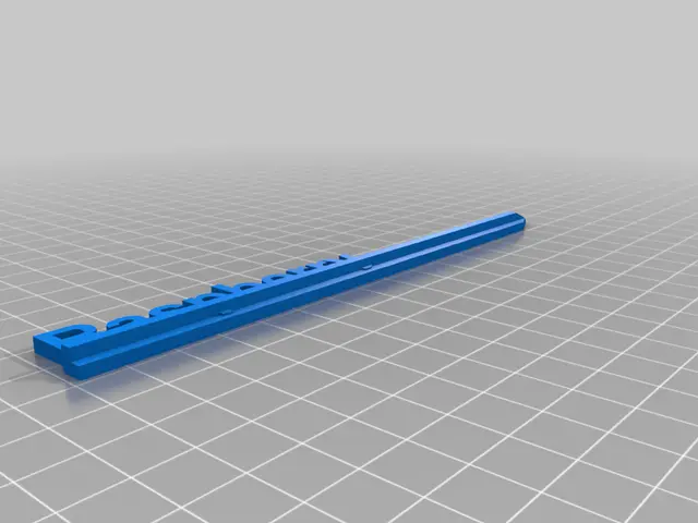
Magnet dimensions alone do not determine holding strength. Magnet quality, steel thickness, coatings, spacing and load direction all affect the result. The foam rubber provides the anti-slip contact needed in my setup, but covering the magnets also increases their distance from the steel. Test the complete combination of magnets, backing and mounting surface. Foam Rubber Cutting Template The included template helps you cut the anti-slip foam rubber to match the back of the mount. Its outline is inset by 0.5 mm on each side, so the backing does not protrude beyond the edges. - Overall size: 89 × 129 mm.
- Template thickness: 2.4 mm.
- Print orientation: Flat on the bed; no supports needed.
- Material: PLA is sufficient.
Place the template on the foam rubber’s protective backing, trace around the outer edge, and cut along the outline. The internal grid saves material and provides rigidity—it is not a cutting pattern. Remove the adhesive liner, align the foam rubber with the mount and press it firmly into place. The anti-slip backing is strongly recommended: my mount slid down the safe wall without it. The template produces a continuous backing without magnet cutouts. Since the foam adds distance between the magnets and the steel, check the holding strength with your chosen foam thickness. Printing The successful print used PLA. The exact slicer settings for that print have not been fully documented. The following are suggested starting settings, not a verified load-bearing print profile: Setting Starting point
Material PLA, as used for the successful print
Layer height 0.20 mm
Perimeters 6
Top/bottom solid layers 6 each
Infill 40–50% gyroid
Temperature and cooling Appropriate profile for your PLA
Supplied STL orientation Rear wall-contact surface facing the bed
Supports Inspect pocket bridges and guide overhangs in the slicer; add local supports where needed
Remove any support remnants from the magnet pockets. With the back facing the bed, printing over the pockets creates bridges; bridge quality affects how far the magnets can be inserted. Changing print orientation can change both fit and strength. Assembly and use - Insert each magnet straight, using even pressure. Do not hammer it in. If resistance is excessive, stop and check the fit and any printing residue.
- Cut out foam rubber using the included template.
- Apply the self-adhesive anti-slip foam rubber to the rear surface, then position the mount on the intended steel surface and check adhesion and sliding resistance.
- Slide the unloaded firearm into the guide from above, checking that it rests on the lower stop and that accessories do not interfere.
- Check that the mount stays in place when inserting and removing the firearm. If it slides or lifts away from the wall, do not use it until the attachment is secure.
Descripción original del autor, publicada en Printables.