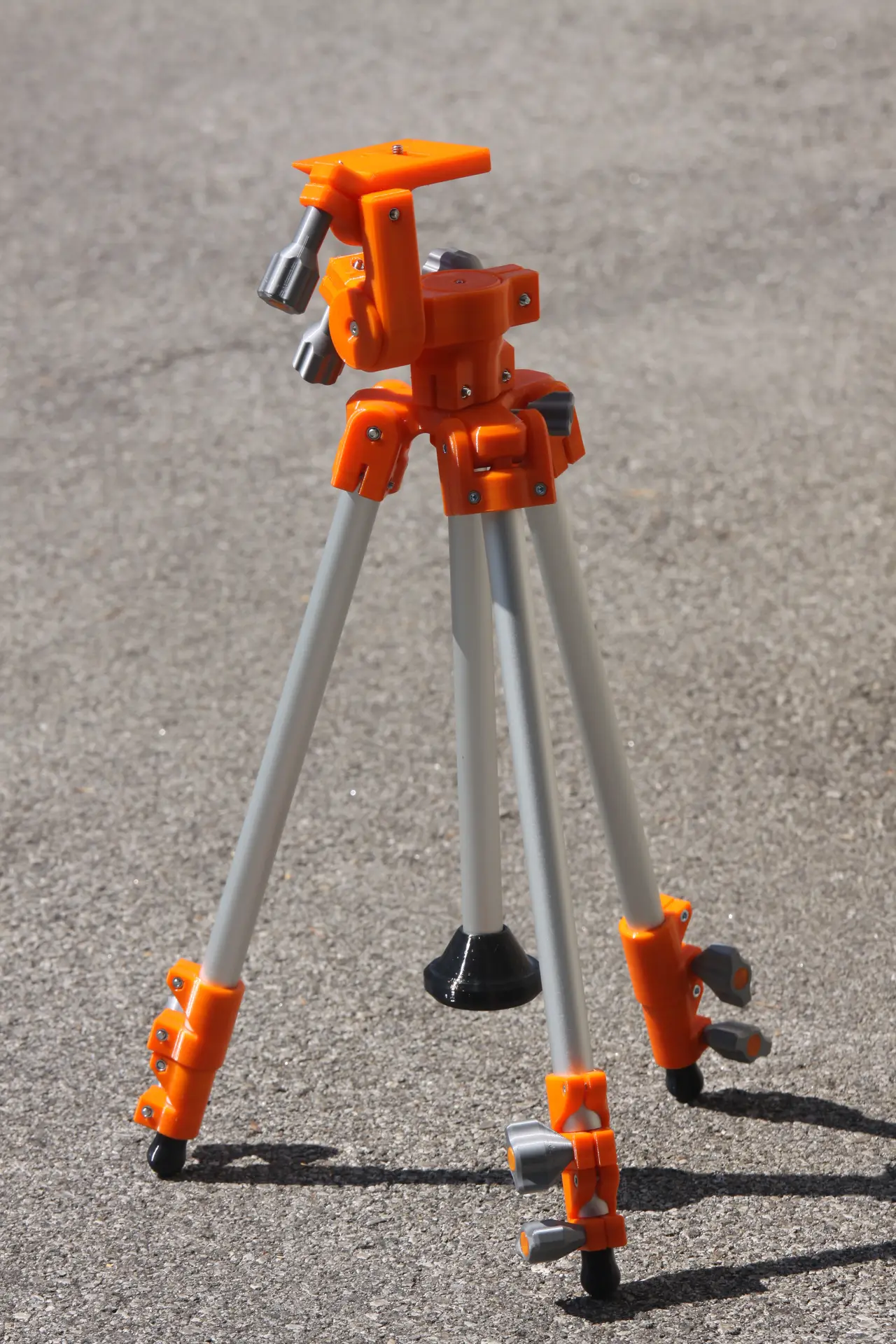
3d printed tripod
por Lytographum en Printables
Tripod with head for video and photography, 3d printable with Petg and TPU.
Licencia
Solo uso personalCC BY-NC-SA 4.0 — Atribución, no comercial, compartir igual
Uso personal dando crédito; sin fines comerciales y las modificaciones con la misma licencia.
Al descargar aceptas respetar la licencia y dar crédito a Lytographum.
Archivos (22)
- Endstop 12.stl STL · 97 KB
- Endstop 16.stl STL · 101 KB
- Column cap.stl STL · 317 KB
- 16 - 20 joint.stl STL · 278 KB
- 12 - 16 joint.stl STL · 218 KB
- TPU cap.STL STL · 25 KB
- Foot.stl STL · 977 KB
- Body.stl STL · 319 KB
- Leg joint.stl STL · 234 KB
- Head joint.stl STL · 512 KB
- Camera base cylinder.stl STL · 98 KB
- Tilting cylinder.stl STL · 119 KB
- Rotating base cap.stl STL · 59 KB
- Rotating base.stl STL · 150 KB
- Camera base cap.stl STL · 62 KB
- Camera base.stl STL · 134 KB
- Tilting head.stl STL · 114 KB
- Knob cap small.stl STL · 25 KB
- Knob cap.stl STL · 26 KB
- Head knob.stl STL · 127 KB
- Column knob.stl STL · 623 KB
- Leg knob.stl STL · 541 KB
- Categoría
- Tecnología
- Formatos
- STL
- Descargas
- 972
- Publicado
Sobre este modelo
PRINTABLE TRIPOD Simple but functional tripod with a maximum extension of about 1,30 meters, design also includes a 3-axis head.
BILL OF MATERIALS
PRINTED PARTS All parts doesn't require supports, also STLs are already oriented for printing. N. PHOTO NAME INFILL PERIMETERS MATERIAL Q.TY
1Body403PETG1 212 - 16 joint403PETG3 316 - 20 joint403PETG3 4Leg joint403PETG3 5Foot202TPU 95A3 6Endstop 12403PETG3 7Endstop 16403PETG3 8Column cap202TPU 95A1 9TPU cap1002TPU 95A1 10Leg knob202PETG / PLA6 11Head knob202PETG / PLA3 12Column knob202PETG / PLA1 13Knob cap202PETG / PLA / TPU9 14Knob cap small202PETG / PLA / TPU1 15Head joint403PETG1 16Rotating base403PETG1 17Rotating base cap403PETG1 18Tilting cylinder403PETG1 19Tilting head403PETG1 20Camera base cylinder403PETG1 21Camera base403PETG1 22Camera base cap403PETG1
TUBES
N° NAME EXT ØINT ØLENGTHMATERIAL Q.TY
2320 - 320 Tube2018320Anodized aluminum4 2416 - 300 Tube1614300Anodized aluminum3 2512 - 280 Tube1210280Anodized aluminum3
SCREW AND BOLTS
N PHOTO NAME Q.TY
26M3 x 10 socket head screw2 27M4 x 16 socket head screw6 28M4 x 25 socket head screw8 29M5 x 45 socket head screw3 30M4 x 25 hex head screw1 31M4 x 35 hex head screw9 32M4 x 40 hex drive flat head screw3 33M3 nut2 34M4 nut10 35M4 locknut12 36M5 locknut3 37Camera screw*1 *For the camera screw I use this (https://amzn.eu/d/7YtbWqY) from Amazon (NOT AFFILIATE LINK)
ASSEMBLY
Knobs assembly
A knob
- Insert an M4 x 35 hex head screw (31) inside leg knob (10); - Push the knob cap (13) inside knob to disguise the screw.
B knob - Insert an M4 x 35 hex head screw (31) inside head knob (11); - Push the knob cap (13) inside knob to disguise the screw.
C knob
- Insert an M4 x 25 hex head screw (30) inside column knob (12); - Push the knob cap small (14) inside knob to disguise the screw.
STEP 1: 12mm leg assembly
- Insert M4 nut (34) inside endstop 12 (6), then slightly screw M4 x 16 socket head screw(27); - Push the endstop inside 12 - 280 tube (25). You will have to use a lot of force; - Now tighten the screw with wrech. With this operation the endstop made more grip with leg beacouse the hexagonal hole is conic and nut push in outside direction.
STEP 2: 12 - 16 joint assembly
- Insert M4 nut (34) and M4 selflock nut (35) inside 12 - 16 joint (2). Pay attention to directions; - Slightly screw M4 x 16 socket head screw(27) and Leg knob (A).
STEP 3: Joint - leg - feet assembly
- Put the leg inside joint from the top; - Press leg into the foot (5).
STEP 4: 16mm leg assembly
- Insert M4 nut (34) inside endstop 16 (7), then slightly screw M4 x 16 socket head screw(27); - Push the endstop inside 16 - 300 tube (24). You will have to use a lot of force; - Now tighten the screw with wrech. With this operation the endstop made more grip with leg beacouse the hexagonal hole is conic and nut push in outside direction.
STEP 5: 16 - 20 joint assembly
- Insert M4 nut (34) and M4 selflock nut (35) inside 16 - 20 joint (3). Pay attention to directions; - Slightly screw M4 x 16 socket head screw(27) and Leg knob (A).
STEP 6: Mounting 16mm leg on 12mm leg
- Insert 16mm leg inside 16 - 20 joint assembly from the top; - Use the knobs on the joints to block it on the leg; - Push 16mm leg inside 16mm hole in 12 - 16 joint then thight M4 x 16 screw for blocking the leg inside joint.
STEP 7: Leg joint assembly
Descripción original del autor, publicada en Printables.